Humanoid AI Teaching Assistant Robot ("Baker Bot")
A life-sized, waist-up humanoid robot built by a 16-person student team to serve as an AI-powered teaching assistant, commissioned by a physics professor at Western University.
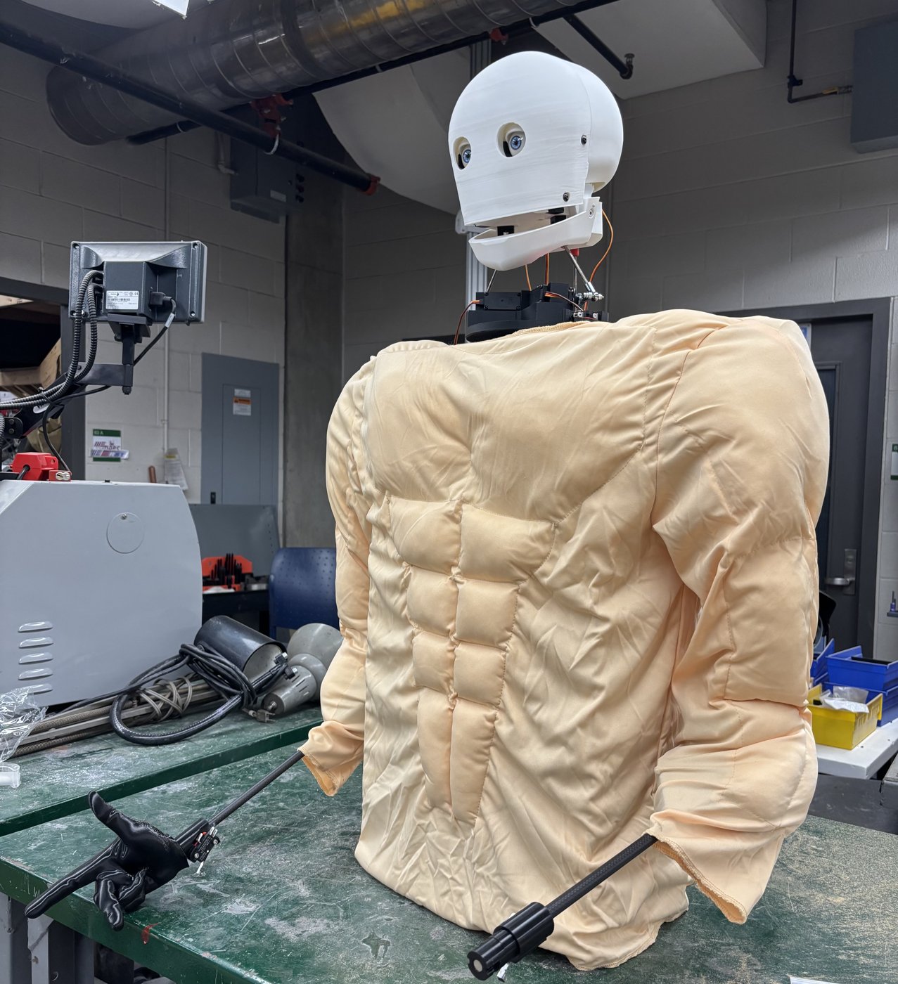
The finished robot in its padded muscle suit.
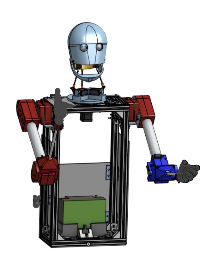
Full assembly CAD, waist-up.
Overview
Baker Bot is a waist-up humanoid robot commissioned by Dr. Mark Baker, a first- and second-year physics professor at Western University, to act as an AI-powered teaching assistant that answers questions and reacts during lectures. A team of 16 students split the build across six subsystems: software, electrical, arms, head, neck, and torso. The finished robot turns and tilts its head, moves its eyelids and jaw, and gestures with both arms while responding to spoken questions. The full build came in under $2,000.
I led the arm subsystem, a two-person team, and served as mechanical manufacturing lead for the whole robot, doing the bulk of the mechanical fabrication and final assembly.
My Contributions
- Designed the elbow joint end to end in SolidWorks: actuation, housing, feedback, and homing.
- Led the shoulder and hand designs, teaching my teammate through the CAD as active mentoring.
- Handled all arm electrical work: motor drivers, limit-switch homing, and potentiometer position feedback.
- Did the full fabrication of both arms.
- Set the print and design-for-manufacturing standards used on every printed part in the arm subsystem.
Interactive CAD Model
The full arm assembly in 3D. Drag to rotate, scroll to zoom.
Arm Subsystem
Each arm has three functional stages: a manually indexed shoulder that sets the working height, a powered elbow that provides the main range of motion, and a swappable hand on the end of a carbon fiber forearm. The design assumes the robot sits at a desk in front of students, so the arm's job is to gesture expressively within reach of the tabletop, not to lift heavy loads.
Five-Position Shoulder Pivot
The shoulder pivots on a single large bolt fixed to the torso. An aluminum plate on the arm carries five holes, and a spring-loaded indexing plunger in the body drops into the chosen hole to lock the shoulder at one of five angles. Because the robot works seated at a desk, this lets the operator set each arm's height to match the table before a session, freeing the powered elbow to handle the expressive motion. Two cut-and-drilled aluminum sheets per arm carry the load into the pivot.
Indexing the shoulder by hand keeps it simple, strong, and power-free, saving the actuation budget for the elbow, where it matters most.
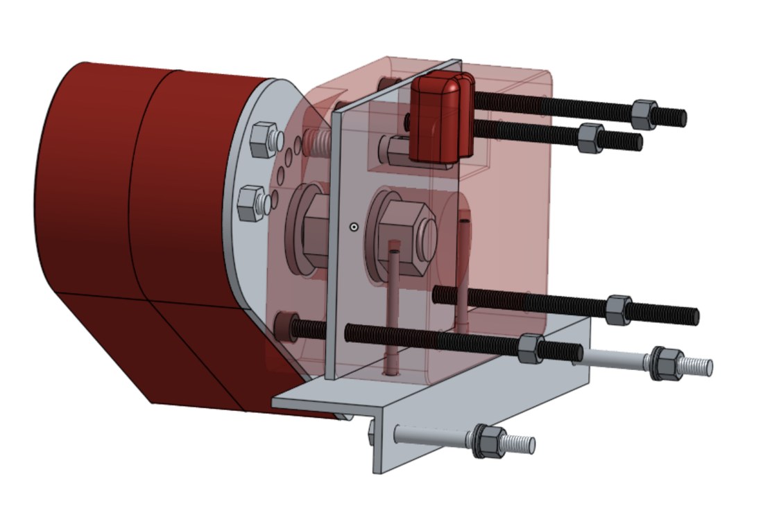
Shoulder pivot internals in CAD.
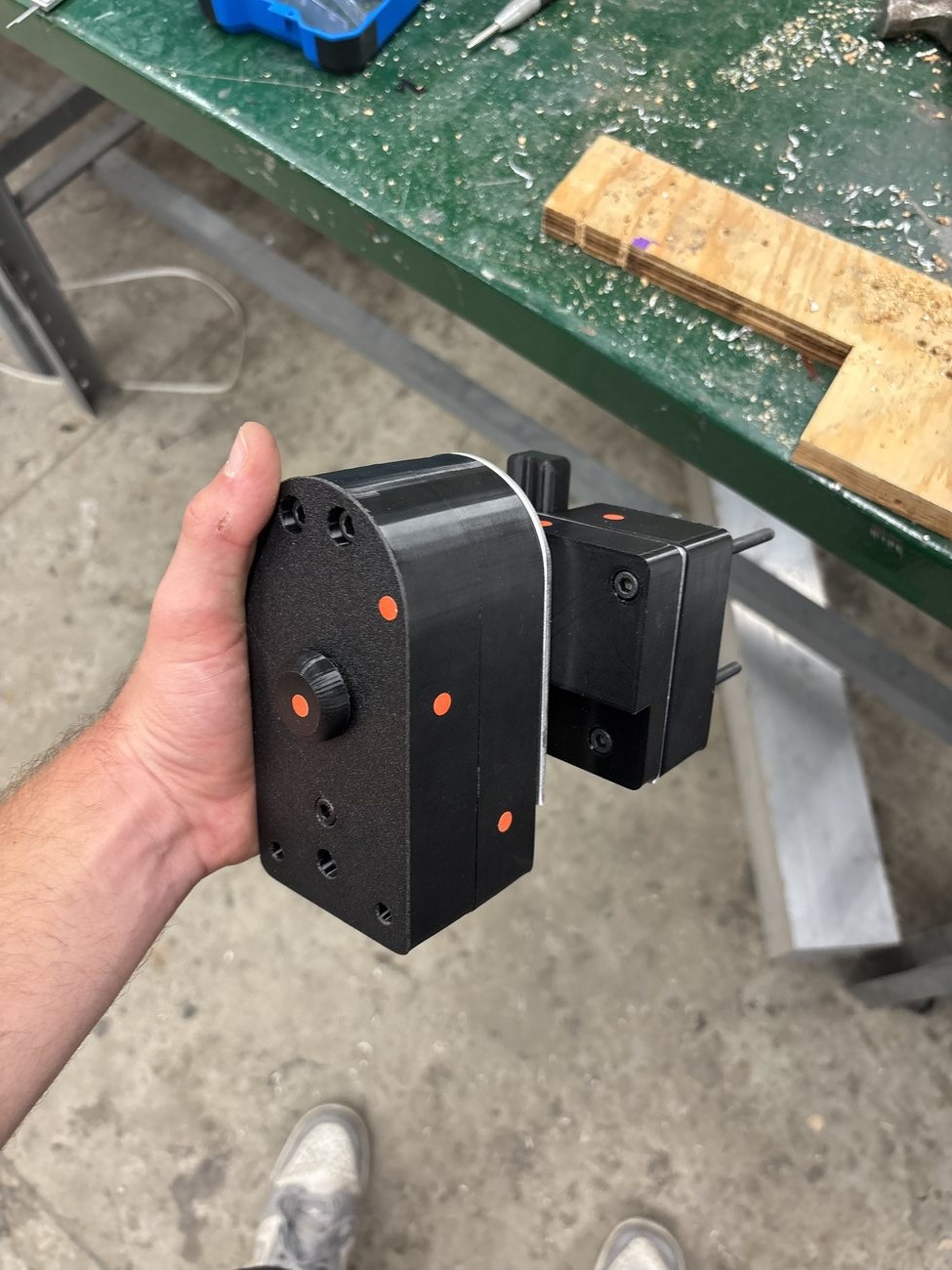
The printed shoulder housing and its indexing plunger.
Non-Backdrivable Elbow Joint
The elbow is the only powered joint in the arm and carries roughly 110 degrees of range. It is driven by a 12V DC worm gear motor. The worm drive is non-backdrivable by design, so the elbow holds any angle at zero holding current: the arm draws no power and generates no heat while posed, which matters for a robot that spends most of a lecture holding a gesture. A potentiometer built into the joint reports elbow angle in real time, so the controller always knows where the forearm is. The whole joint is built from seven 3D-printed parts that fit together around the motor, potentiometer, and limit switch to form one compact, self-contained module.
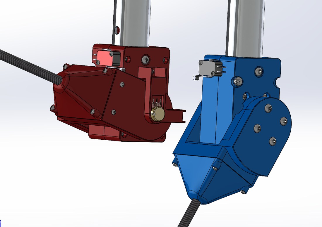
Elbow CAD: worm gear motor, limit switch, and potentiometer.
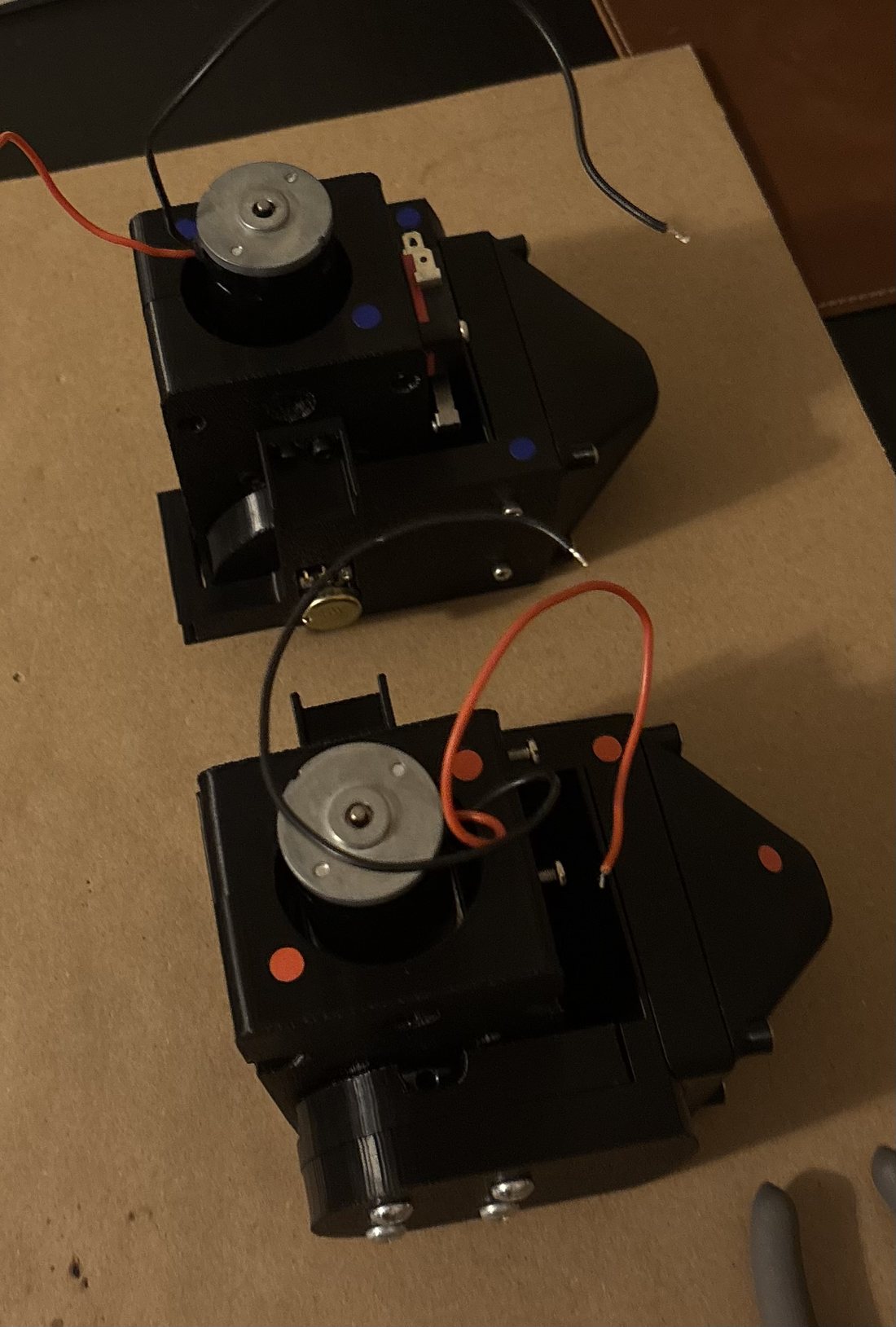
Both assembled elbow modules.
Sizing the Elbow
The forearm and hand hang off the elbow as a cantilever, so the joint only has to hold their weight at full extension.
- Carbon fiber forearm tube (10mm outer diameter, 8mm inner, 420mm long): about 20 g
- Printed hand: about 200 g
- Static holding moment at full extension: about 0.9 N·m
The selected worm gear motor is rated near 3 N·m, giving roughly a 3x safety factor on the static hold, with the non-backdrivable worm carrying the load at rest instead of the motor.
A same-size aluminum forearm would weigh close to double. Keeping the forearm light with carbon fiber keeps the elbow moment low, which is what lets a small, low-power motor hold position for a full lecture. Tip deflection of the carbon tube under the hand's weight is only about 2 to 3 mm, so the arm stays visually rigid while gesturing.
Forearm and Swappable Hands
The forearm is a carbon fiber tube, chosen for stiffness at low weight. The hand mounts to the end through a quick-swap interface: a keyed turn-to-lock collar with a magnet that holds the hand seated. This lets the robot change hands for context: a right-hand-rule hand for physics demonstrations, an open pointing hand for gesturing and explaining, and a closed hand that can hold an object. Because the interface is shared, new hands can be designed and swapped in later, so the robot can be customized for special occasions. The hands themselves are printed and fixed rather than actuated, a deliberate scope cut to stay on budget without losing the expressive value of a posed hand.
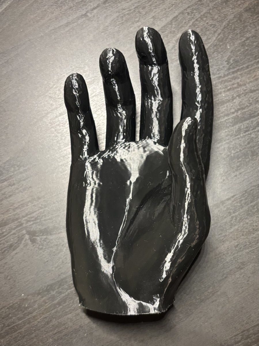
A printed swappable hand, open palm.
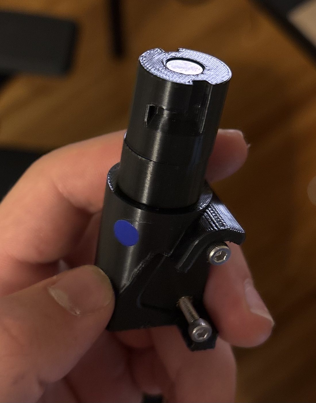
The quick-swap hand mount.
Homing, Feedback, and Gesture Control
I handled all of the arm's electrical work and integrated it into the robot's shared control system. At startup, a homing routine sweeps each arm until limit switches trigger, establishing the elbow's zero reference and the height of the table in front of the robot. During use, the in-joint potentiometer provides live elbow position. The arm's 12V worm gear motors run through a DC motor driver commanded by the system's ESP32-WROOM-32 controller, with the elbow potentiometer and limit switches wired back to that same board. Power comes from a 12.8V LiFePO4 battery, stepped down through buck converters on the electrical subsystem's power distribution board.
Gestures tie into the AI pipeline. An onboard Jetson Orin Nano handles speech-to-text and text-to-speech and passes each question to an external AI model, which returns a response plus an emotional tag. The robot speaks the answer while the arms play the gesture mapped to that emotion. Head and neck servos are driven separately through a PCA9685 PWM controller.
Design for Manufacturing
Every structural part on the robot was 3D printed, so I set a manufacturing standard that made parts come off the printer ready to assemble, with no cleanup and no failed fits. Details I built into every part:
- Chamfered bottom edges to cancel elephant's foot, so parts sit flat without filing the first layer.
- Teardrop-shaped horizontal holes, so they print cleanly without support and hold their diameter.
- Chamfered heat-set insert holes, giving the plastic displaced during insertion somewhere to go and keeping the surface flush.
- Tuned clearances for press fits and fasteners, with printed test-fit coupons for every critical interface before committing to a final part.
I printed and assembled the complete arm subsystem along with parts of the head and neck, prototyping in PLA to iterate cheaply and reprinting final parts in PETG for strength and temperature tolerance, roughly 50 unique printed parts across the robot. The non-printed structure I fabricated by hand: cutting and drilling the aluminum upper-arm tubes and shoulder plates, and cutting the carbon fiber forearms to length.
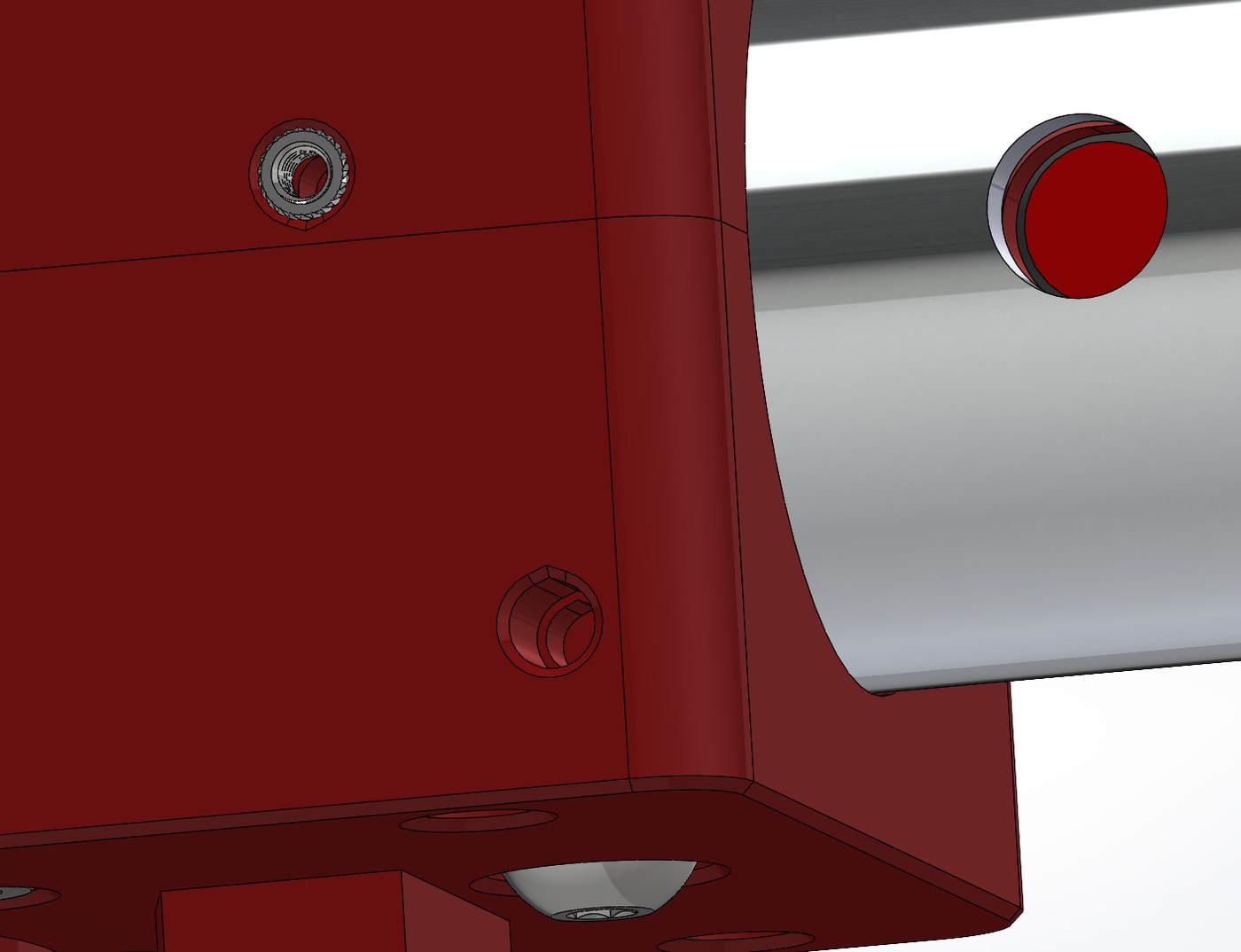
An elbow part, showing the print details built into every part on the arm.
Leading the Subsystem
Leading a subsystem taught me to break a build into realistic long-term and short-term goals: near-term targets that keep a teammate learning and shipping at a steady pace, set early enough to leave room for team review and revision before integration. I taught the shoulder and hand designs through the CAD itself, so the knowledge stuck and the work held up. Balancing my own design and fabrication load against mentoring and whole-robot assembly was the core challenge, and it is the part of the project I would point to for any team-based engineering role.
Being both arm subsystem lead and mechanical manufacturing lead for the whole robot meant moving between CAD, electrical wiring, firmware, and a 3D printer farm in the same week, and being accountable for how well those pieces fit together at final assembly, not just for my own arm. A 16-person student build with a sub-$2,000 budget also has no room for a part that has to be redesigned after it is printed, which is why the manufacturing standards, the sizing math on the elbow, and the shoulder and hand mentoring all point the same direction: get it right on paper, with a tested reason behind the choice, before committing material or a teammate's time to it. That mix of technical range, budget discipline, and ownership past the edge of my own subsystem is what I'd bring to any team building real hardware on a deadline.
Autonomous Collection & Sorting Robot
A two-machine system that sweeps green erasers off a set, slightly uneven floor area, carries them back to base, and sorts them by colour with no human input and no remote control. Built in eight weeks for a second-year design competition, where it placed 2nd.
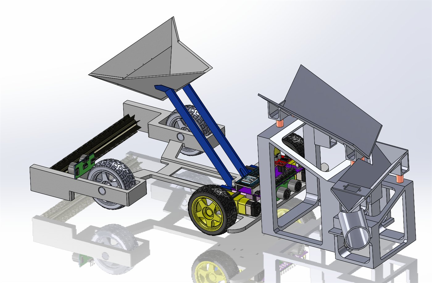
Full system CAD, scoop raised over the sorting station.
The same assembly in 3D. Drag to rotate, scroll to zoom.
Overview
The competition brief gave us 120 seconds, a set area of roughly 15 m², and a slightly uneven floor scattered with erasers. The system had to locate and collect them, tell green erasers apart from every other colour, and deposit them into the correct bin at a home base, entirely on its own, with scoring tied to both how many it collected and how accurately it sorted them.
The decision that shaped everything else was splitting those two jobs across two machines. A mobile scavenger robot drives the area and sweeps up erasers without trying to identify anything, and a stationary sorting station at the home base does all the colour classification. Collection is fast and indiscriminate; sorting is slow and careful. Neither job compromises the other.
The sorting station was mine end to end: mechanical design, electronics, and firmware. My teammates built the scavenger.
My Contributions
- Designed and built the stationary sorting station end to end: vibratory feed, colour sensing, and the diverter chute.
- Wrote the colour classification algorithm: illumination-invariant normalized RGB behind six simultaneous gates, with a one-second temporal confirmation before the chute commits.
- Wrote the station's firmware in Arduino C++ on an ESP32, built entirely around a non-blocking state machine.
- Handled the station's electrical work: motor drivers, sensor wiring, PWM channels, and power.
- Tuned the feed as a system: spring rate, motor speed, and the timing offset between the two vibrating stages.
Why Sort at the Base Instead of Onboard
We scored three full system concepts through a Go/No-Go screen and then a weighted decision matrix. Onboard sorting kept failing the same way: a colour sensor riding on a moving robot sees changing ambient light, vibration from the drivetrain, and erasers tumbling past at unpredictable angles. Every one of those degrades a colour reading, and a misread costs points directly.
Moving the sensor to a fixed station fixes the sensing environment: consistent geometry, consistent lighting, one eraser presented at a time. The cost is that the robot has to come back to base, but it already had to, because that is where the bins are.
The Sorting Station
The station takes a scoop-load of mixed erasers dumped in at the top and processes them one at a time. Two inclined V-shaped platforms vibrate the pile into a single-file line, with a drop between them that breaks apart whatever is still stuck together, a colour sensor reads each eraser as it reaches the bottom, and a servo-driven chute swings to send it left or right.
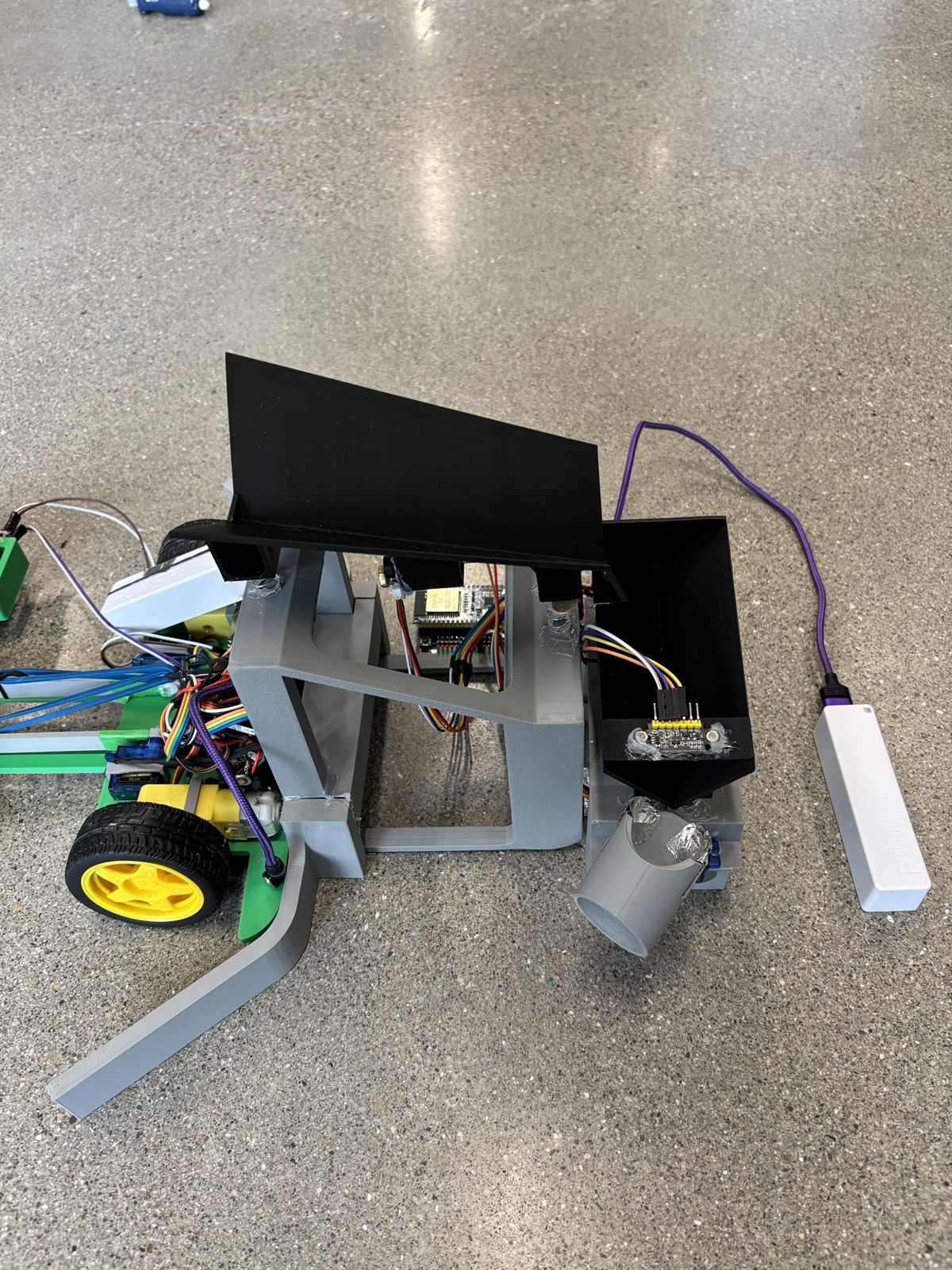
The feed platform, and the chute with the colour sensor at its mouth.
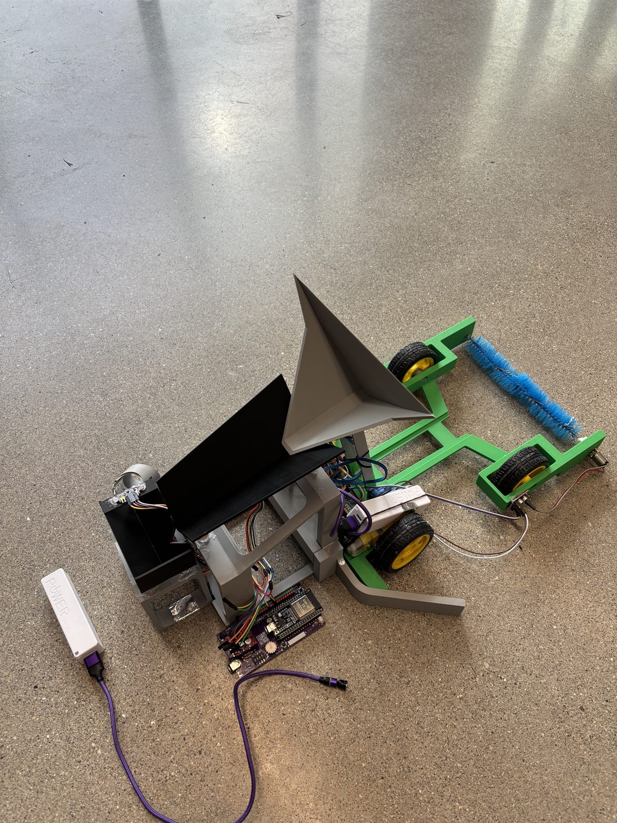
The robot tipping its scoop onto the feed ramp.
The station separating, reading, and diverting erasers.
Two-Stage Vibrating Feed
The feed is two V-shaped platforms in series, each with its own vibration motor, and a short drop from the first into the second. The arrangement is borrowed from industrial sorting lines: potato and produce graders use staged vibrating beds with transfers between them, because one bed on its own will not reliably present a single item. The V walls channel the pile into a line, and the drop between the stages knocks apart anything still stuck together on the way down.
Neither vibration motor is a vibration motor. Each one is an ordinary DC gearmotor with a hex nut glued to the encoder disc on the back of the motor shaft, upstream of the gearbox, where the shaft still turns at the motor's own speed rather than the reduced output speed. An offset mass spinning that fast is the entire working principle of a vibration motor, and putting it before the reduction is what makes it work at all: the geared output turns far too slowly to shake anything. Two nuts and some glue stood in for a part we did not have.
Each V sits on four springs, and the spring rate mattered as much as the motors did. Too soft and the platform wallowed without moving anything along; too stiff and it barely moved at all. Getting erasers to index down one at a time meant tuning spring rate and motor speed together rather than either on its own.
The two stages are also deliberately out of phase: the firmware runs motor one for 500 ms, then motor two for 500 ms, with no gap between. The reason is the drop. An eraser leaving the first V while the second V is also shaking lands on a moving surface and bounces, sometimes back up the incline, sometimes straight past the line. Offsetting the two means the platform receiving an eraser is always the one holding still.
The Two-Position Chute
At the bottom, a single servo drives the chute between two fixed positions: 0° for non-green and 70° for green. There is no in-between and nothing to calibrate at runtime. The chute rests in the non-green position, so a sensing failure or a power glitch defaults to the reject path rather than contaminating the green bin.
Indexing One Eraser at a Time
Nearly every hard problem on this machine sits upstream of the sensor. Classifying is the easy half: given one eraser, held still, under fixed light, calling it green or not green is close to solved. Getting exactly one eraser to arrive, alone, is what took the iterations.
Erasers are close to a worst case for a feeder. They are rectangular blocks with flat faces and square edges, so they neither roll nor flow. A heap of them locks together instead of pouring, and it will bridge across the full width of the ramp and sit there indefinitely. The faces are also large relative to the mass behind them, so two erasers in contact have a great deal of surface holding them together and very little weight trying to pull them apart.
Then there is the rubber itself, which is engineered to grip. Erasers stick to the platform, stick to each other, hold static, and shed dust that makes the surface grippier as a run goes on. That leaves the ramp angle with no good setting: shallow enough to meter erasers out individually and the pile simply stops moving, steep enough that it always moves and the whole clump slides down as one body. Gravity and geometry alone never separated them. The separation had to come from the vibration and from the drop between the two stages, which is why the feed ended up staged rather than as one long shaking ramp.
This is also where the residual error lives. On single erasers the classifier does not miss; in full runs the system sorts at 90–92%. Essentially all of that gap is the feed rather than the sensor: when a whole scoop-load lands at once, two erasers occasionally reach the aperture stuck together and the sensor reads a blend of the two. Every improvement we made to sorting accuracy after the first week was an improvement to feeding, not to the algorithm.
Colour Classification in Six Gates
The sensor is a TCS34725 running over I²C at a 50 ms integration time and 4× gain, and each decision averages three consecutive reads to damp sensor noise. The important step happens before any threshold is applied: the raw red, green, and blue counts are normalized against their own sum, so what the algorithm actually compares is each channel's share of the total light rather than its absolute value.
That one change is what makes the classifier survive real conditions. A green eraser under a bright lab light and the same eraser in shadow produce very different raw counts but nearly identical normalized ones. Absolute thresholds would have needed recalibrating every time someone turned on a different bank of lights in the room.
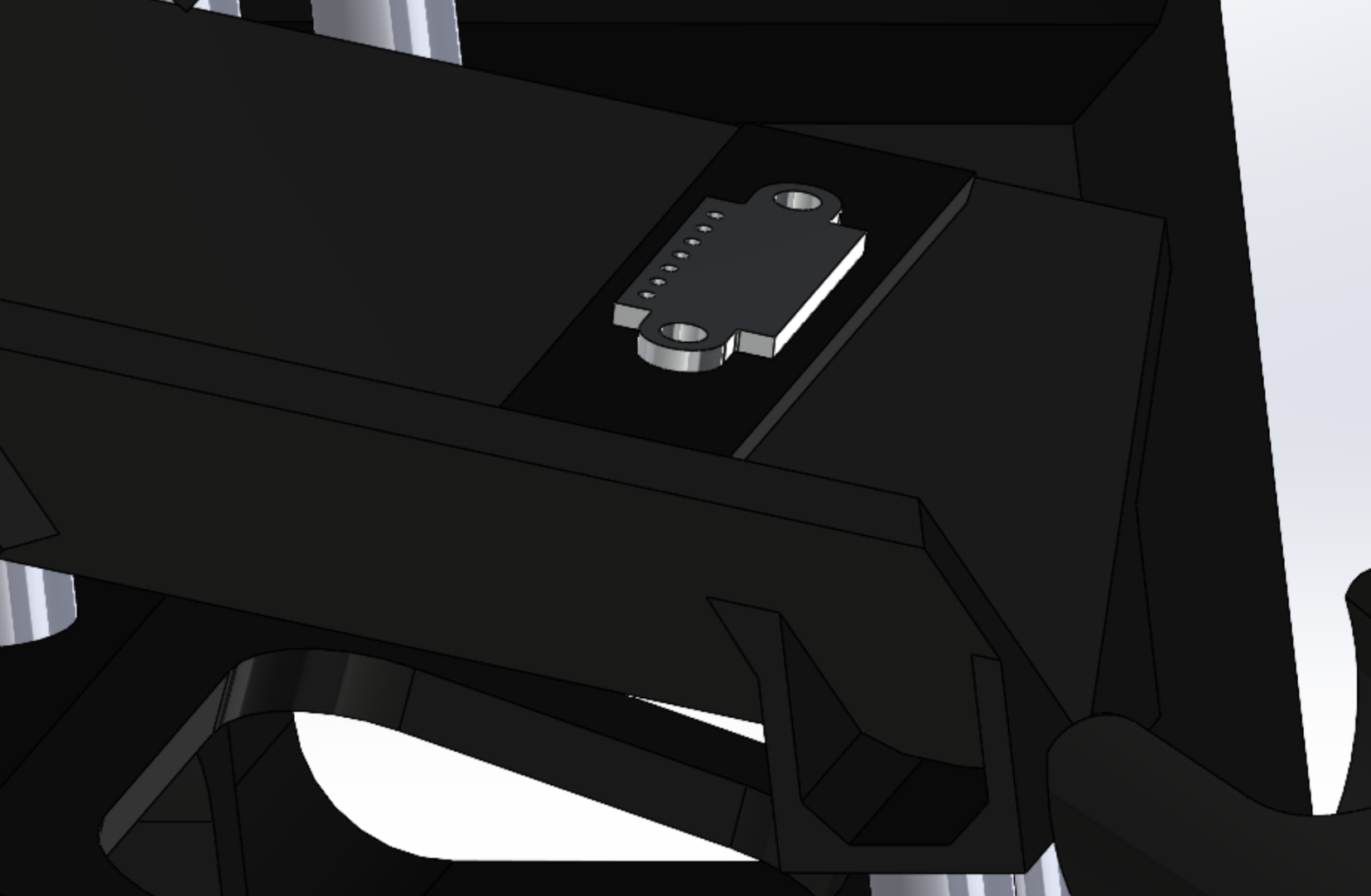
The sensor board recessed into the chute wall.
On top of the normalized values, an eraser has to clear six independent gates simultaneously to be called green. Any single failure rejects it:
| Gate | Threshold | What it rejects |
|---|---|---|
| Clear channel | ≥ 120 | An empty chute with nothing under the sensor |
| Normalized green | ≥ 0.40 | Anything not predominantly green |
| Normalized red | ≤ 0.32 | Yellows and oranges |
| Normalized blue | ≤ 0.32 | Teals and cyans |
| Green dominance | ≥ 0.080 | Greys and washed-out neutrals |
| Hue angle | 108–145° | Yellow-greens and blue-greens at the edges |
The gates overlap on purpose. Green dominance, the normalized green share minus whichever of red or blue is larger, catches the case where a colour is technically green-leaning but so desaturated that it is really grey. The hue window catches the opposite case: a colour saturated enough to pass the channel tests but sitting at the yellow or blue edge of green. A single threshold on green alone would let both through.
Mounting mattered as much as the thresholds. The TCS34725 has to sit close to the eraser, because its reading falls off quickly with distance and starts picking up whatever else is in view, so the board is recessed into the chute wall with its face level with the gap the eraser passes through. Everything around it prints in black, which keeps stray colour from bouncing into the reading and gives the sensor a consistent dark background to read a coloured object against. That proximity is also why the feed springs ended up stiffer than the feed alone would have wanted: a softer spring fed slightly better but shook the sensor enough to smear the reading, and a still sensor was worth more than a marginally better feed.
The One-Second Confirmation Hold
Passing the gates once is not enough to move the chute. The reading has to stay green continuously for a full second before the servo commits, and it has to stay non-green for a full second before the chute swings back. An eraser tumbling past the sensor, a shadow crossing the aperture, or a momentary reflection all produce single-frame misreads, and none of them survive a thousand-millisecond hold.
This is the cheapest reliability improvement in the whole project: a few lines of timestamp comparison that eliminated essentially every false trigger we saw on the bench. Across more than a thousand bench samples, the classifier produced no misclassifications.
The Collection Robot
The scavenger is a 3D-printed rear-wheel-drive chassis with two DC gear motors, a rotary brush across the front, and a servo-actuated scoop. The brush sweeps erasers back into the scoop as the robot drives forward, and reverses direction when the robot backs up so that the erasers already collected stay in rather than being swept back out. It averaged eight to nine erasers per collection pass.
A full autonomous run, collection through sorting.
Designing in Iterations
Fast physical prototypes were what got us to a working design. Model a version in SolidWorks, print it that night, test it on the bench the next morning, change the model the same day. A part in your hand tells you things a CAD model will not, especially with a material as awkward as eraser rubber, and once a rough version worked the same loop was what turned it into a good one. Almost nothing on the finished system is a first revision, and the parts that decided whether it worked went through several each: the scoop, the feed platforms, and the chute.
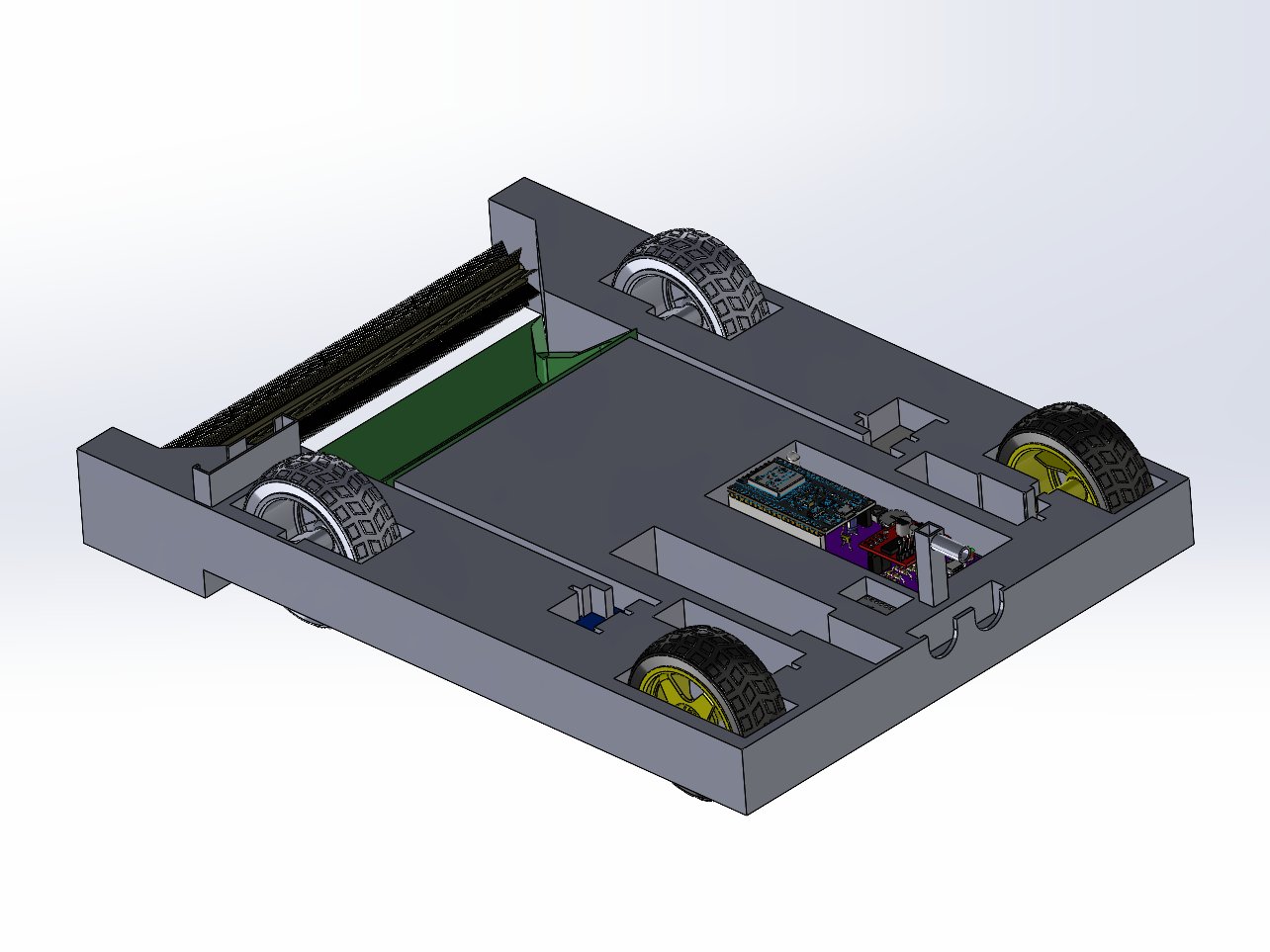
The scavenger's heavy first design, before the weight rework.
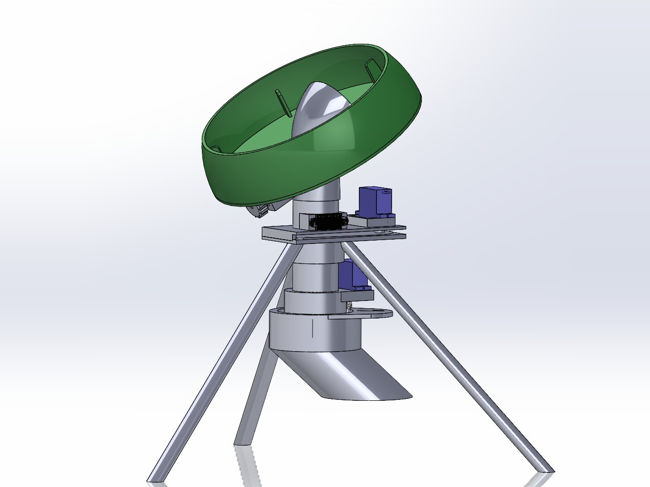
The sorter's first design: a tilted rotating funnel.
Neither machine resembles its first model. The rotating funnel above is a centrifugal bowl feeder in miniature, and it is a completely reasonable way to single-file parts, as long as those parts slide. Once there were printed erasers-and-plastic tests on the bench it was obvious that no amount of spin walks a sticky rubber block up a smooth wall in an orderly line. The vibrating platforms that replaced it were simpler and far more reliable, and they took one less servo to build. The first scavenger went the same way: it was a heavy robot, and keeping the robot light was one of the competition objectives, so what shipped was reworked around minimising weight.
That is the part worth keeping from this project. The binding constraint was not CAD time, it was how many times we could afford to be wrong before the deadline, so we optimised for that: keep every part cheap to print, keep the models easy to re-cut, and never let a single idea carry so much work that killing it hurts. A wrong design cost us an evening instead of a week, and the machine that placed 2nd is essentially the one that survived the most rewrites.
Firmware Architecture
The station's firmware is a single non-blocking loop driving an explicit state machine, with nothing blocking execution while it waits. That matters here because the vibration motors and the colour sensor have to run concurrently: the motor cycle cannot stall colour reads, and a colour read cannot stall the feed. Each keeps its own timestamp and advances independently, which is also what makes the 500 ms offset between the two feed stages exact.
The scavenger runs the larger program, built the same way: 27 states covering three collection passes, each one a sequence of drive out with the brush running, pre-lift the scoop to trap the load, reverse to base, align, lift fully, dump, lower, and turn to the next heading. The scoop lifts in timed one-degree increments every 25 ms rather than being commanded straight to its target, so the load is not thrown out by a sudden servo slew. During the reverse leg the scoop holds a 50° mid-lift, high enough to retain erasers but low enough to clear the station on approach.
Letting the Mechanism Absorb the Error
Our early design assumed closed-loop heading control for navigation. What actually shipped is dead reckoning: timed drive segments, a per-motor PWM trim to correct the chassis pulling to one side, and a potentiometer to tune overall drive speed between runs.
Position accuracy comes from the ultrasonic sensor and the station geometry instead. The robot reverses until the ultrasonic reads 15 cm from the base, then keeps driving for a fixed five seconds while a pair of funnel-shaped guide rails on the station physically pull the chassis into alignment. Rather than measuring the error and correcting for it in software, the rails mechanically remove it. It is a less sophisticated answer than closed-loop control and a considerably more reliable one over a 120-second run.
Source and Documentation
Full firmware for both machines, CAD, engineering drawings, circuit schematics, and the complete design report are on GitHub.
High-Entropy Alloy Catalysts for Seawater Splitting
A noble-metal-free high-entropy alloy catalyst engineered for overall alkaline seawater splitting, developed under Dr. Amir Mirzaei in Western's Department of Physics.
Overview
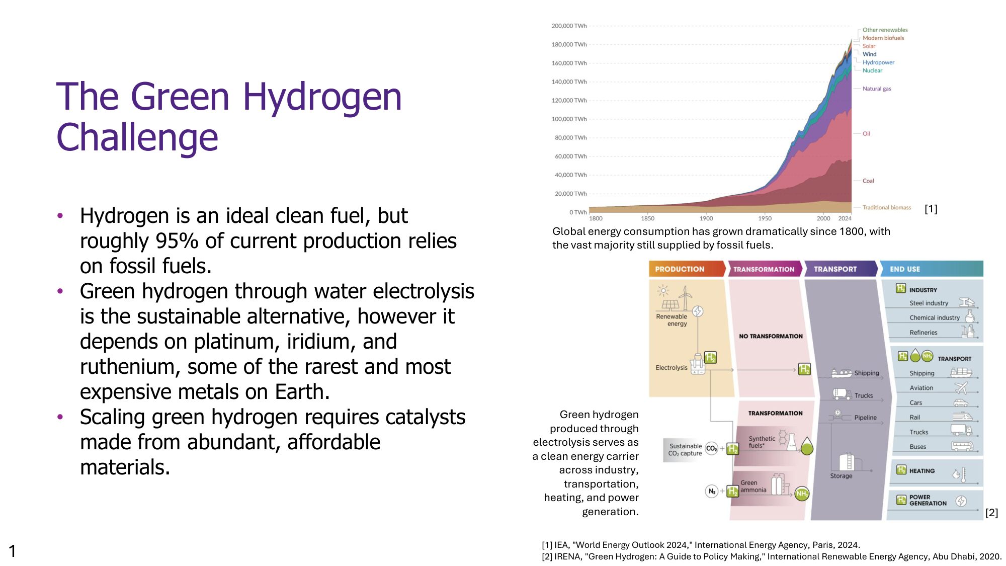
About 95% of hydrogen production today still relies on fossil fuels, and the catalysts that make green hydrogen viable through water electrolysis are usually made from platinum, iridium, or ruthenium, some of the rarest and most expensive metals on Earth. Scaling green hydrogen means replacing them with catalysts made from abundant, affordable elements, and doing it with seawater rather than freshwater, since freshwater is a limited resource while seawater is effectively infinite. My project, under Dr. Amir Mirzaei in the Department of Physics, was to design and optimize exactly that: a bifunctional catalyst for overall alkaline seawater splitting built entirely from earth-abundant metals. In parallel, the lab also had me working on high-entropy oxide semiconductors for photocatalytic hydrogen evolution, a related but separate thread not covered in the presentation below.
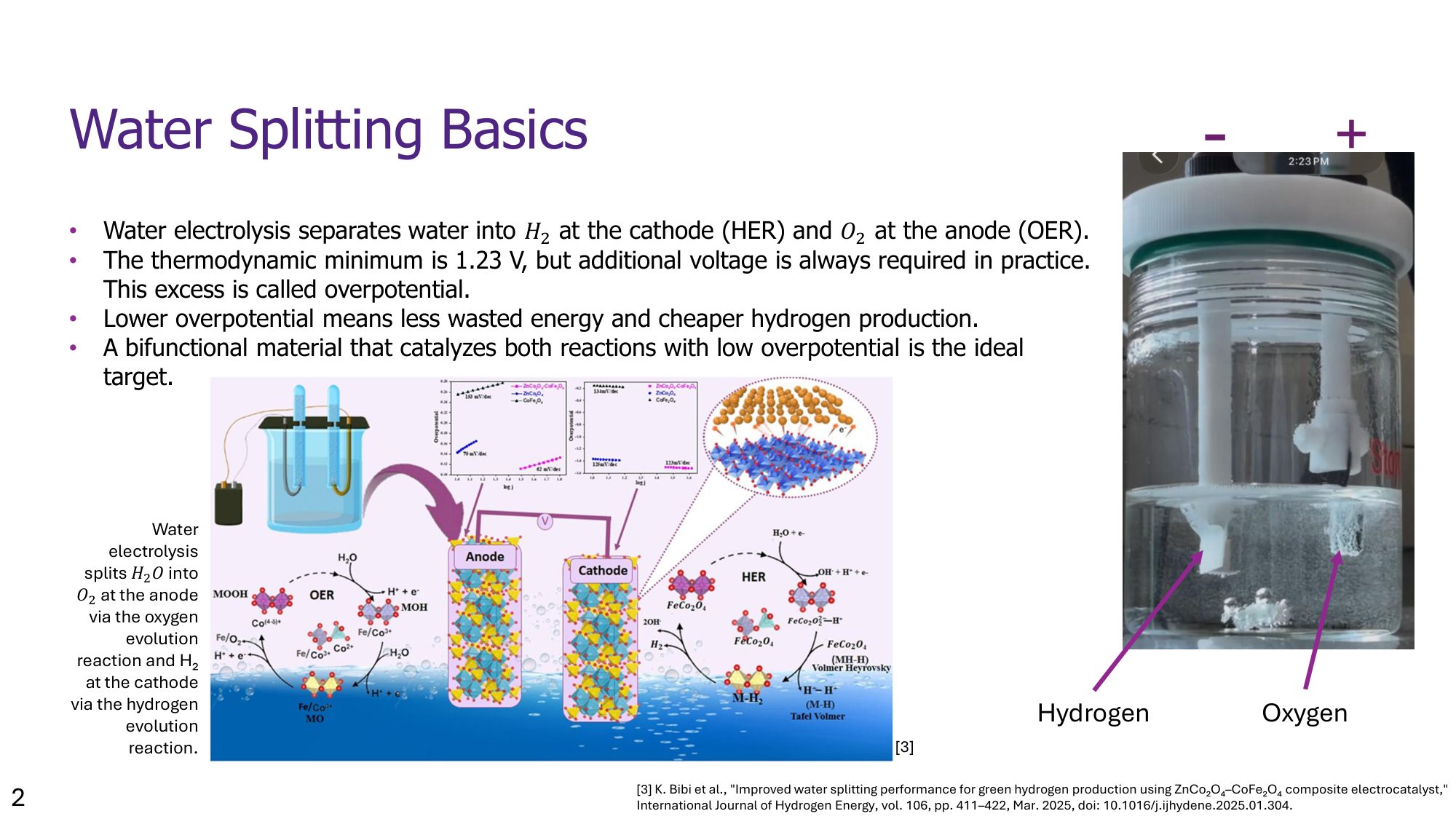
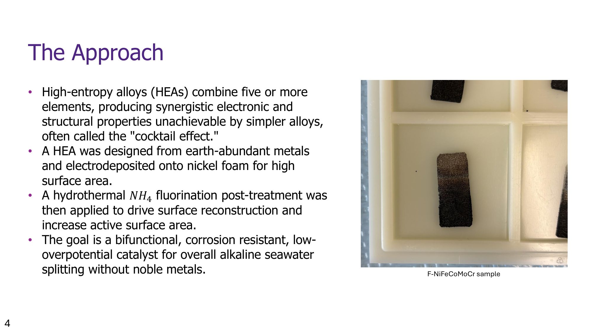
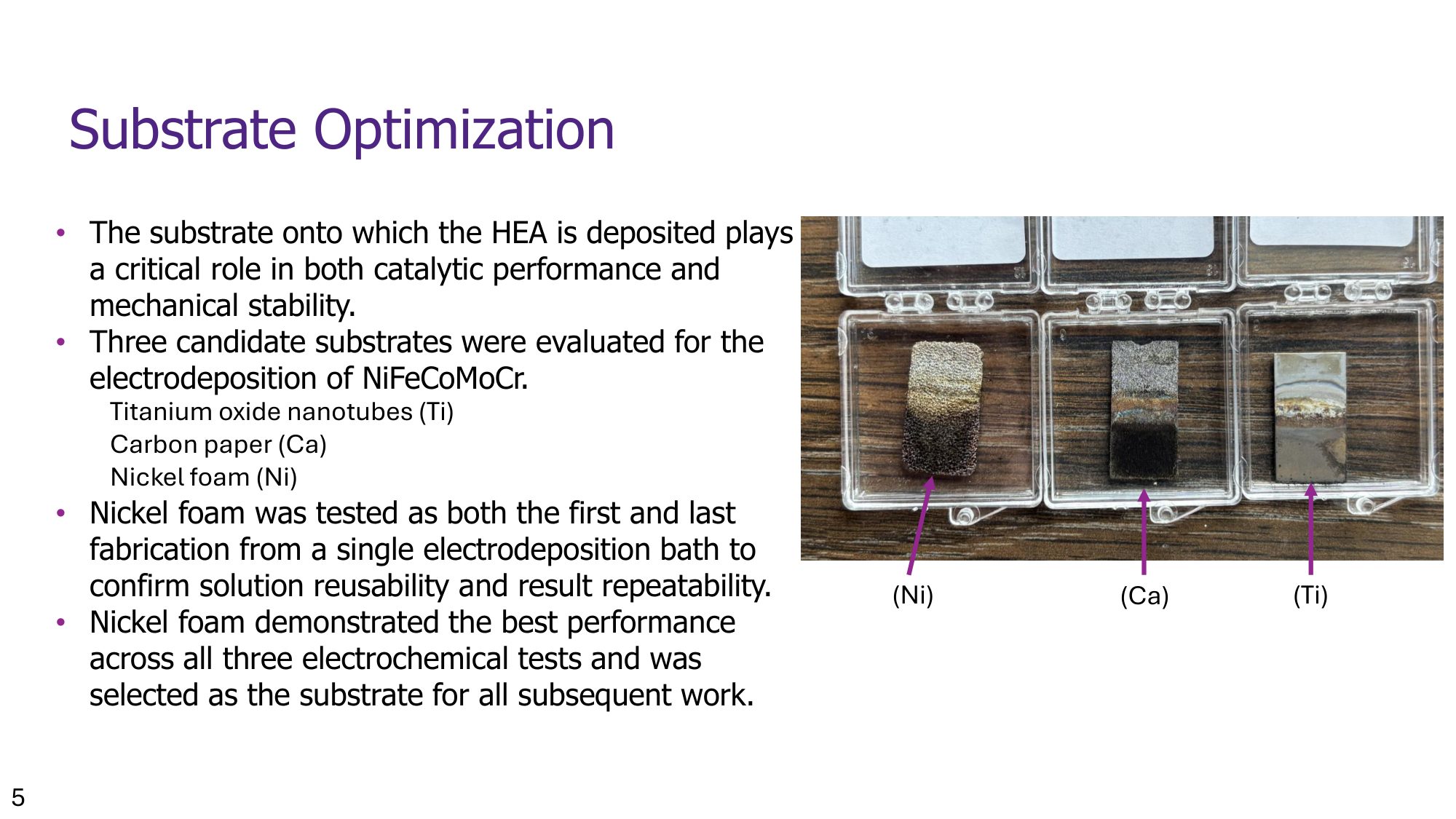
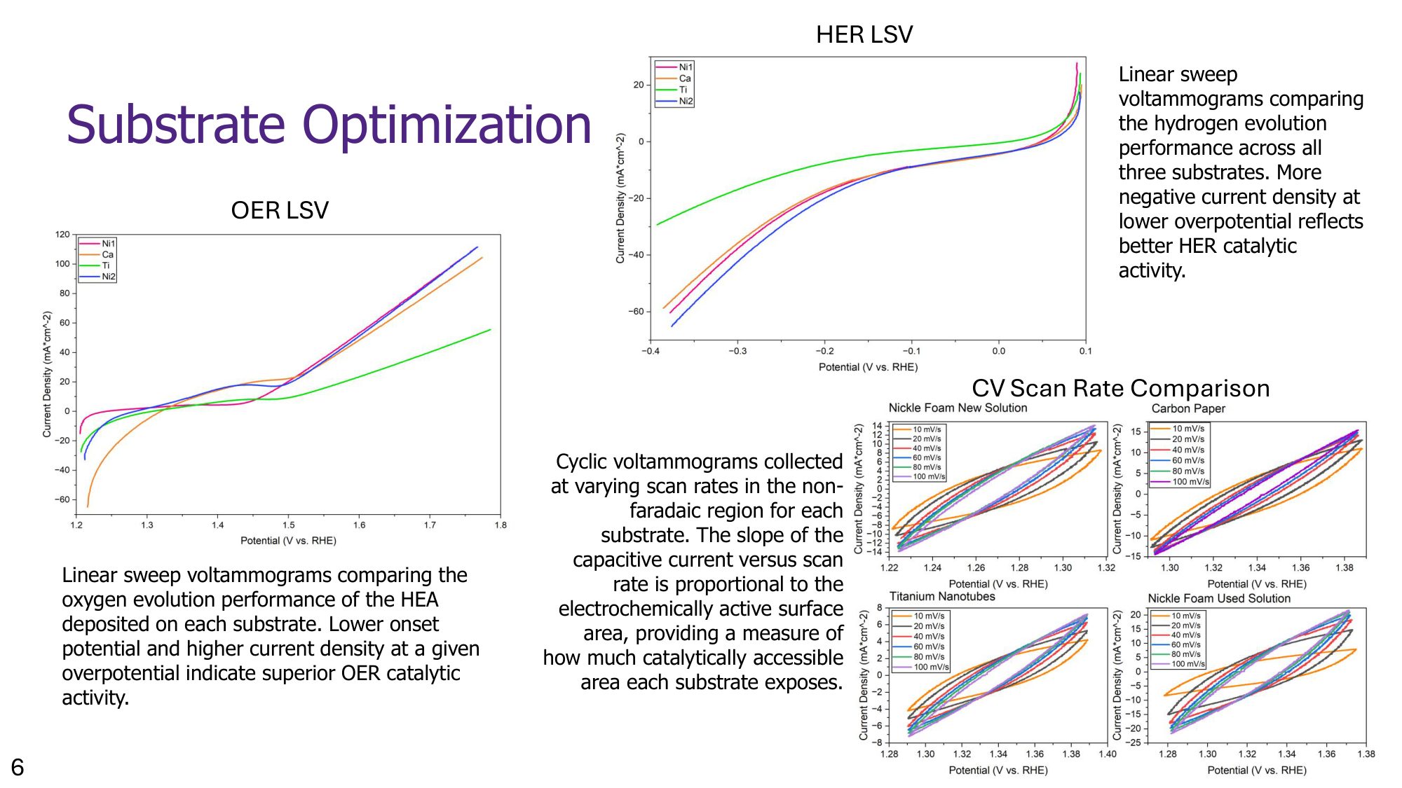
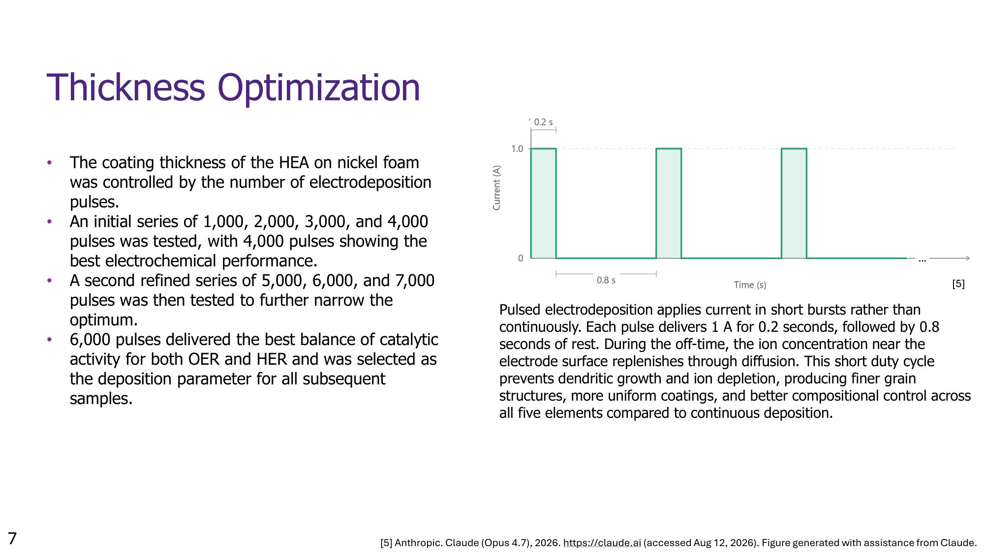
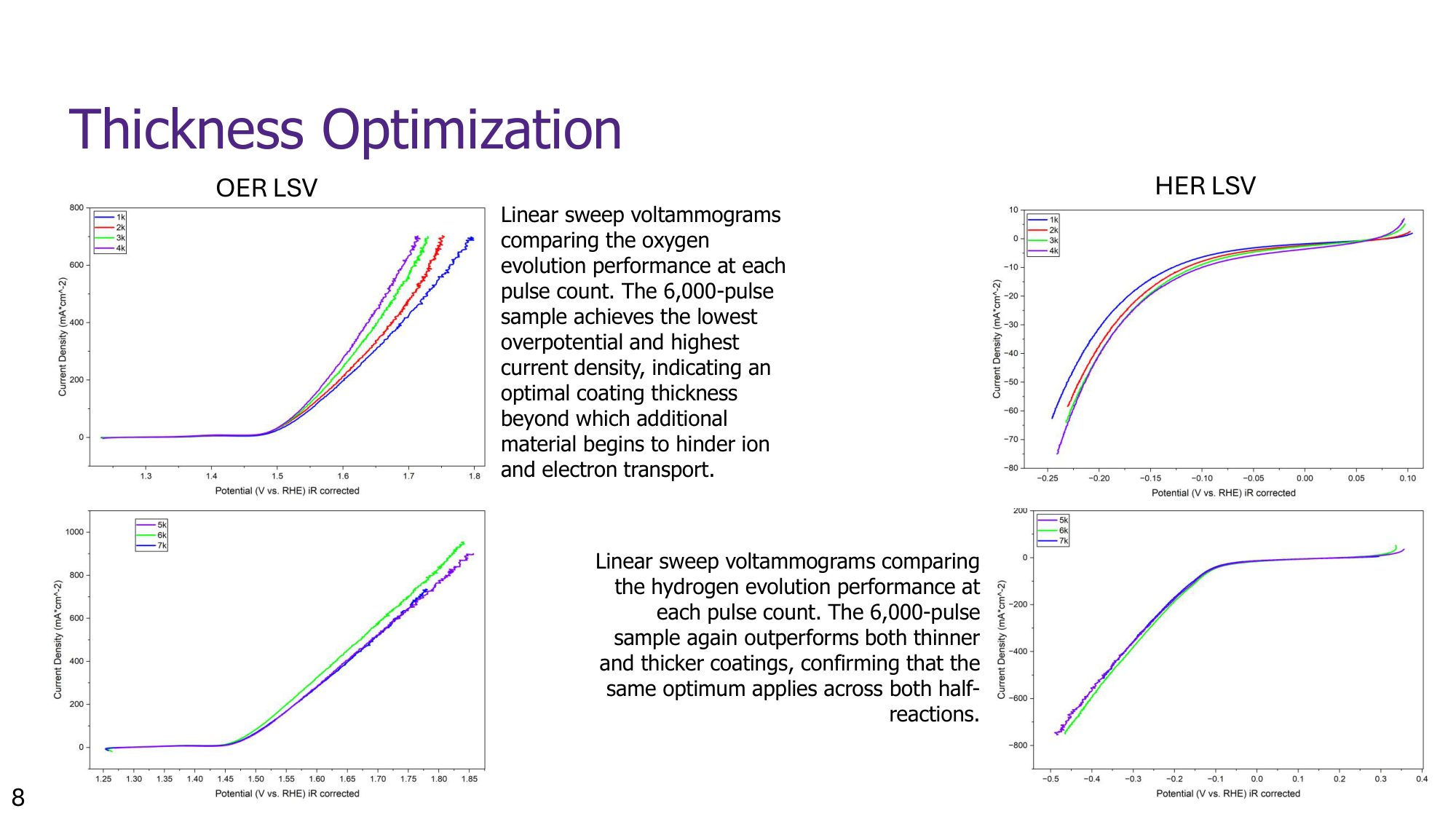
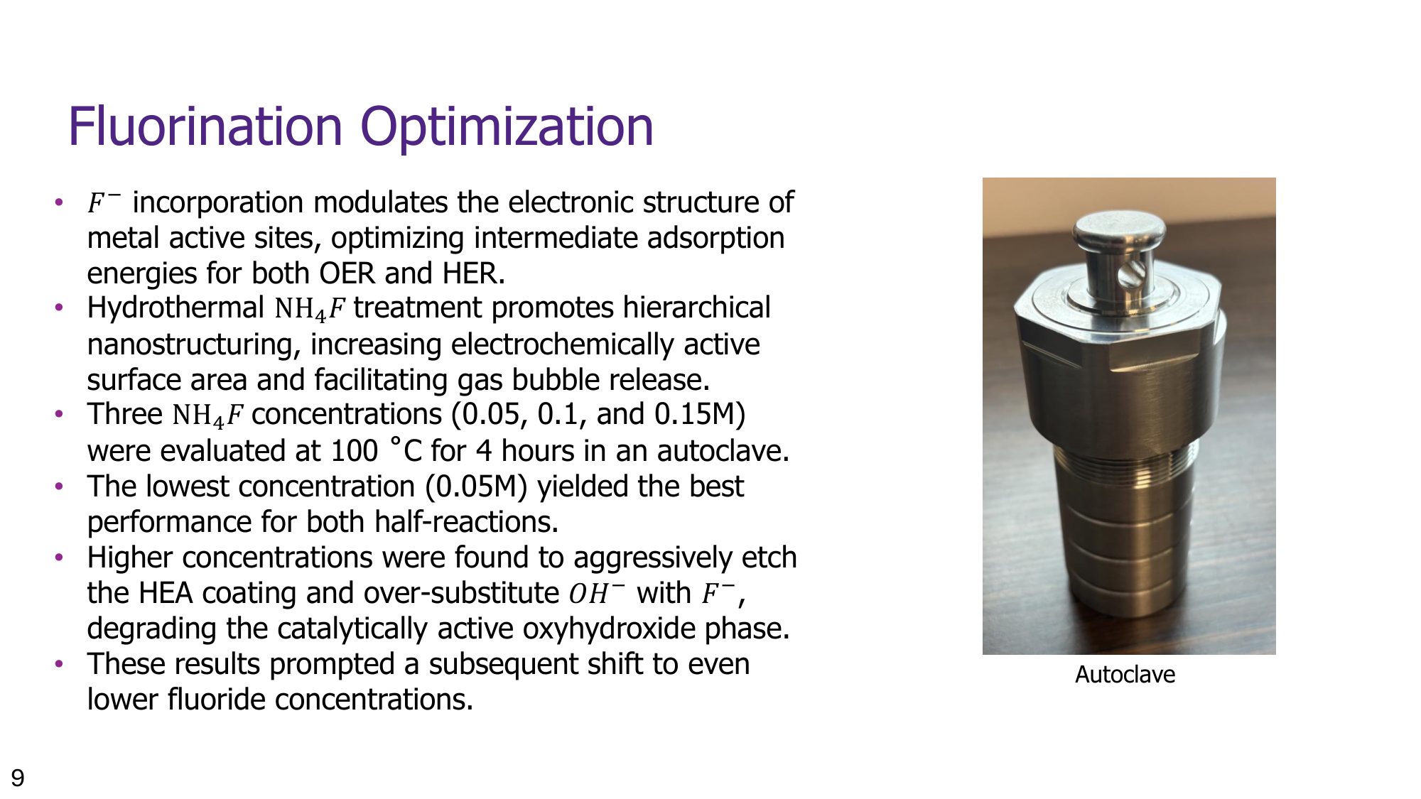
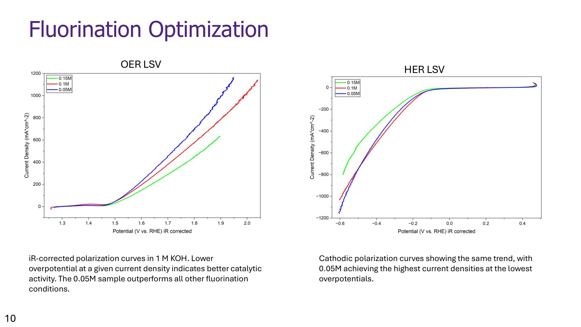
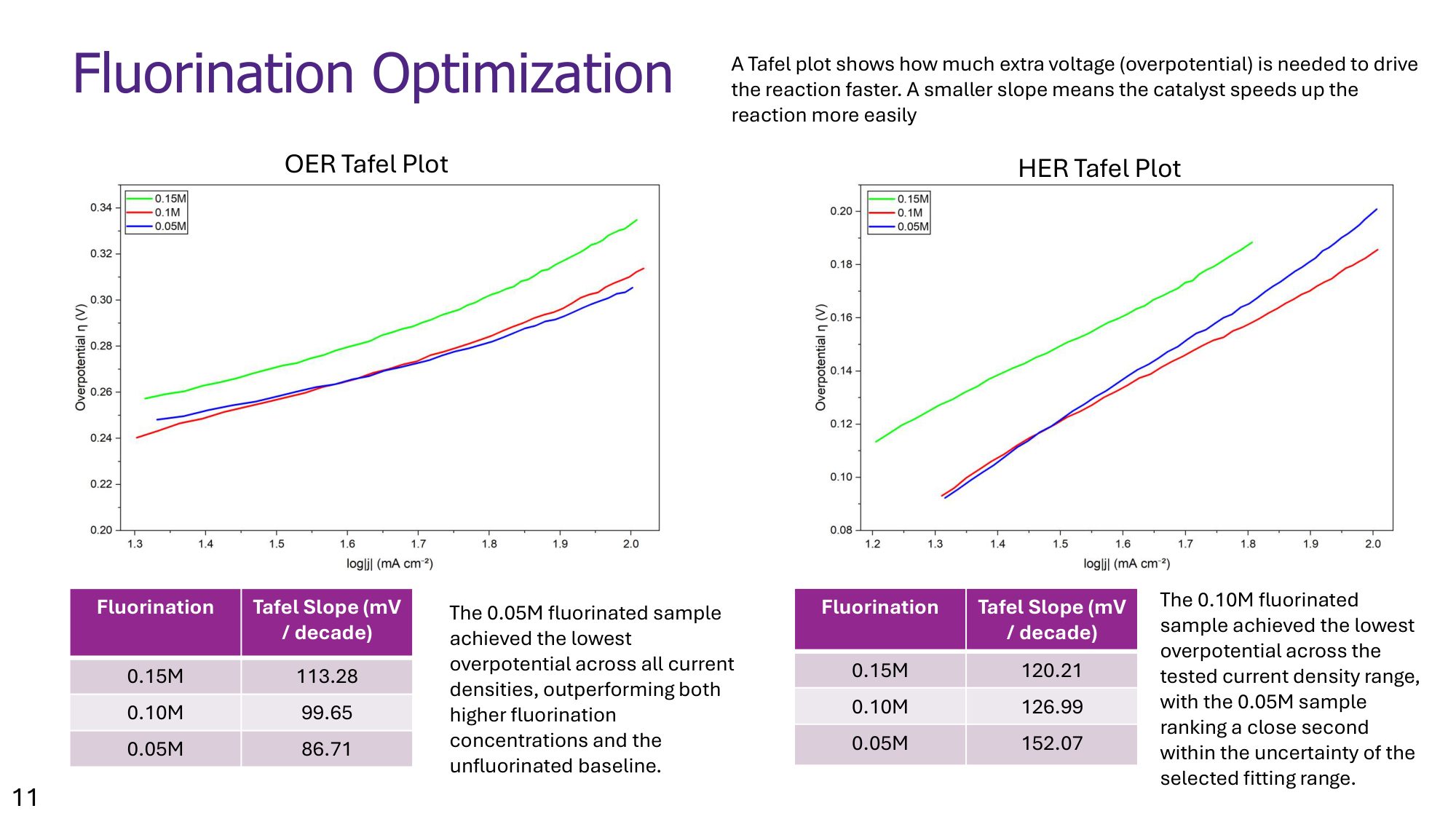
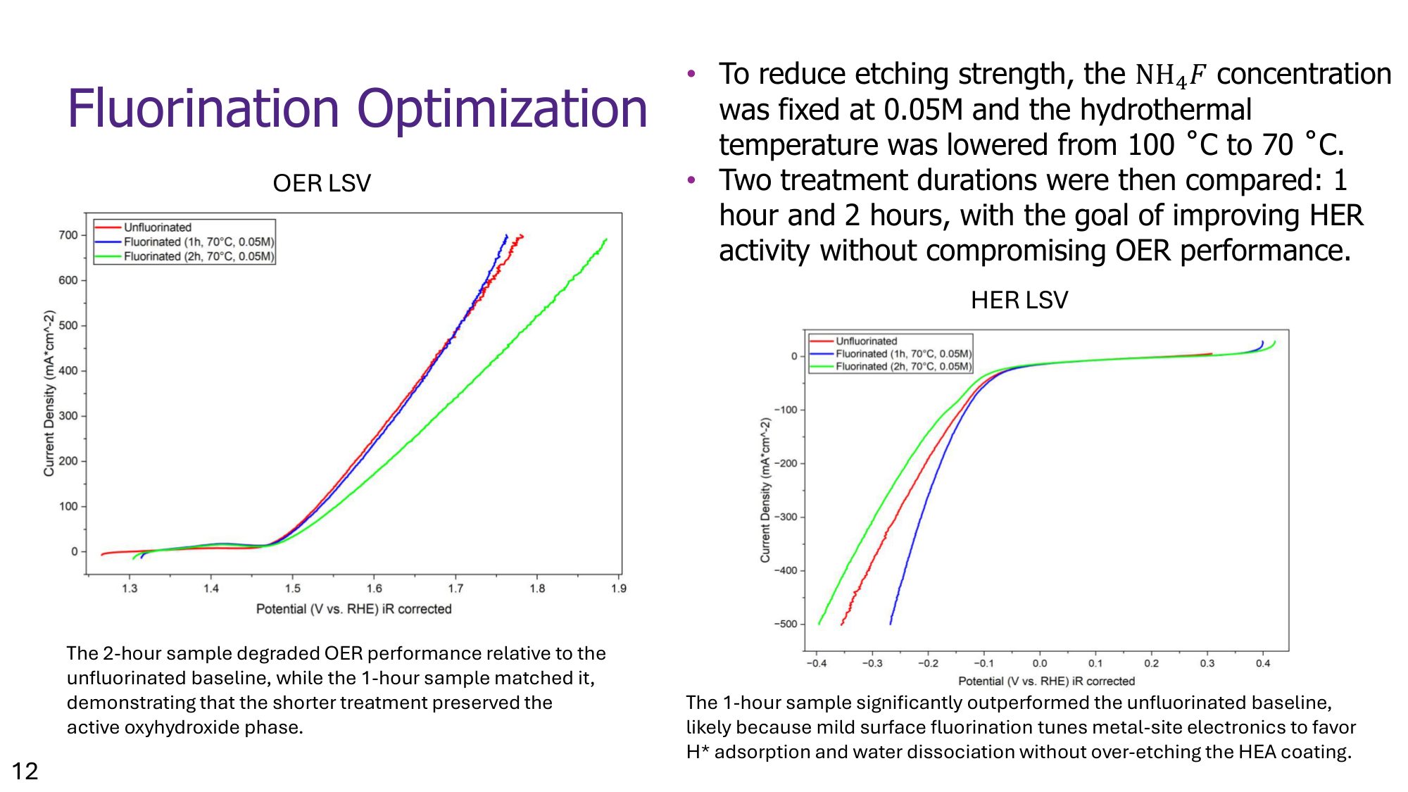
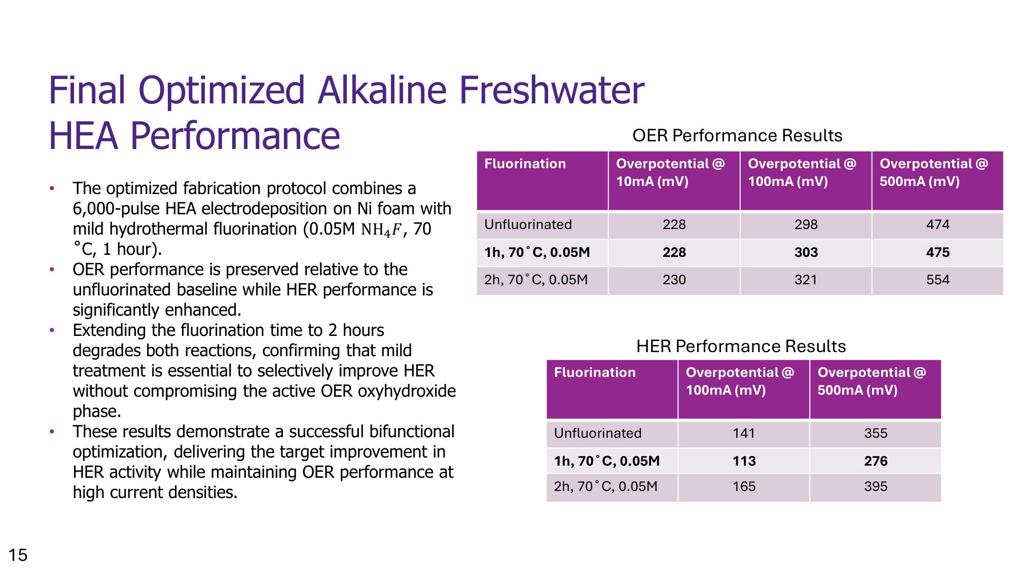
The catalyst is a high-entropy alloy (HEA), NiFeCoMoCr, electrodeposited onto nickel foam for high surface area. HEAs combine five or more elements into one alloy, which produces electronic and structural properties, the "cocktail effect", that none of the individual metals have on their own. I used AI and machine learning to process literature and experimental datasets and narrow down which metal combinations were most promising before committing lab time to them. Once the composition was set, I ran a systematic, iterative optimization of the fabrication process: testing nickel foam against titanium oxide nanotubes and carbon paper as substrates, sweeping electrodeposition pulse counts to tune coating thickness, and finally applying a hydrothermal ammonium fluoride treatment to reconstruct the surface and expose more active area. Each stage was evaluated by electrodepositing samples and testing them with linear sweep voltammetry, cyclic voltammetry, and Tafel analysis on a potentiostat, narrowing in on nickel foam, 6,000 electrodeposition pulses, and a mild 0.05M fluorination step as the best-performing combination.
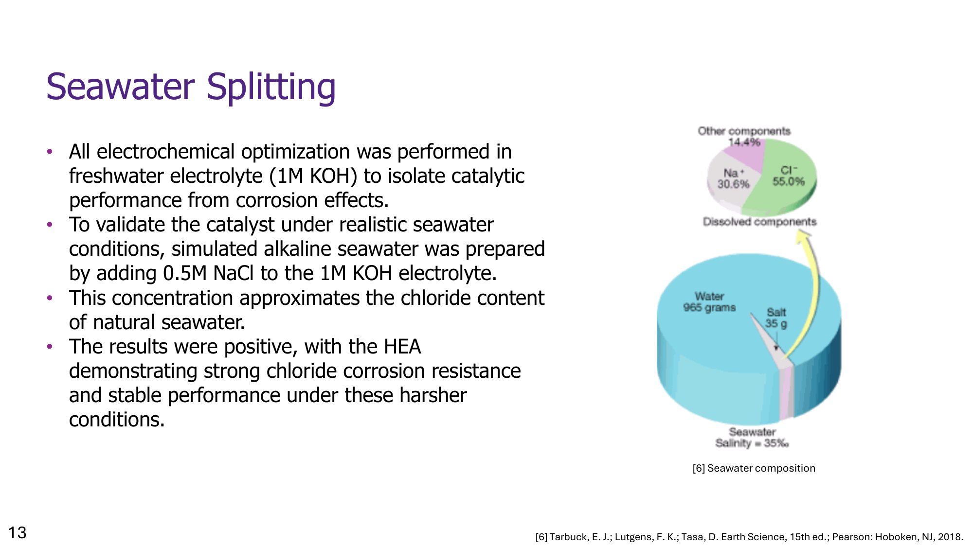
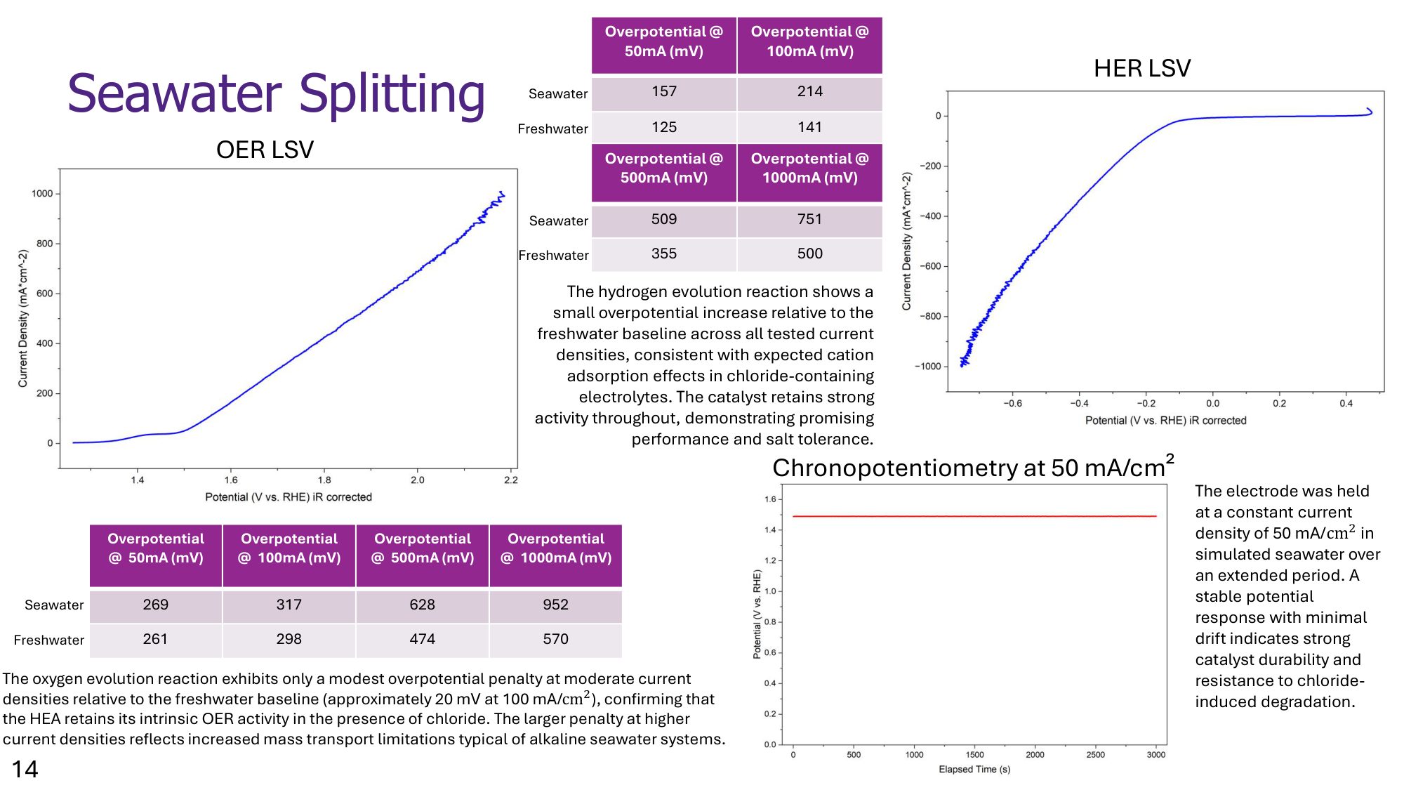
I validated the optimized catalyst in simulated alkaline seawater (1M KOH with 0.5M NaCl added to approximate natural seawater chlorides) rather than just clean freshwater electrolyte, and it held up: strong resistance to chloride-driven corrosion and a stable potential over extended chronopotentiometry testing. Benchmarked against five recent high-entropy alloy catalysts from the literature and against noble-metal standards (RuO2 and Pt/C), the final catalyst matched the best oxygen-evolution performance and exceeded every catalyst in the comparison, noble metals included, on hydrogen evolution. I presented these results at Western's 2026 USRI Research Conference, and they're now being carried forward for publication, with an incoming student continuing the work in the lab.

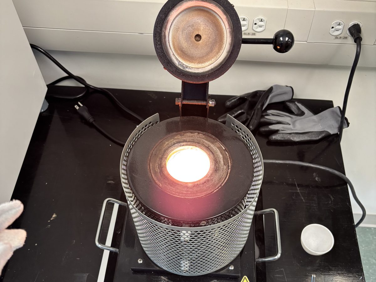
My coworkers in the research lab.
Hydrogen and oxygen evolving off the electrodes during a bench-scale electrolysis test.
Presentation
A short presentation covering my work in more depth.
Click to view the full presentation.









Split Drive Shaft (Western Baja SAE)
A two-U-joint drive shaft for Western Baja SAE's four-wheel-drive off-road car. Splitting the shaft lets the engine sit about 6 inches lower, bolted straight to the frame. My own project, designed for the team's 2027 car.
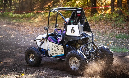
The team's current car at competition.
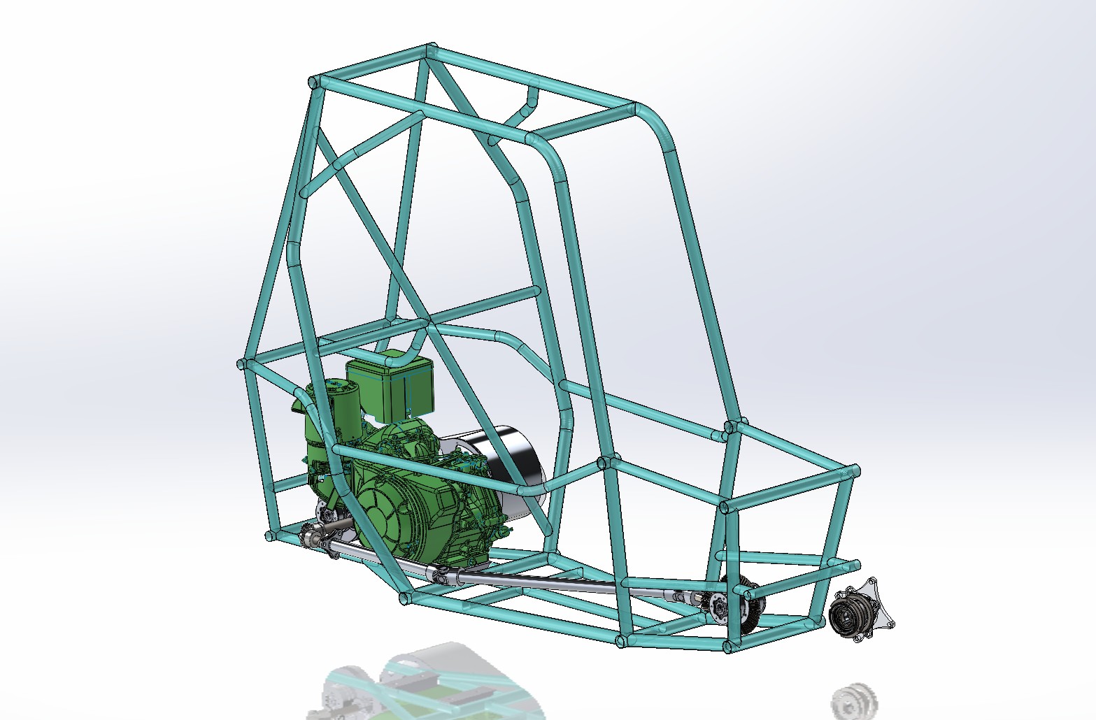
The new frame in CAD, engine dropped low at the rear.
Overview
Western Baja SAE designs and races a single-seat off-road car in the Baja SAE series, which runs endurance races, hill climbs, and suspension courses over rough terrain. The car is four-wheel drive, so power has to get from the gearbox at the back of the car to a front differential at the front. In 2026 I competed with the team at Baja SAE New York in June and Baja SAE Ohio in September.
With a one-piece shaft, the gearbox output and the front differential have to line up in a straight line, which forces the engine to sit high in the frame. My split drive shaft removes that constraint. The shaft leaves the gearbox off to one side of the car, angles across through a U-joint at each end, and arrives at the front differential on the car's centreline. That frees the engine to drop about 6 inches and mount directly to the lower frame, which makes the mounting stronger, lowers the centre of gravity, and opens room to lower the driver's seat too.
I packaged the shaft in the frame, set the joint geometry, designed the custom yokes, and planned the validation and testing that has to happen before it goes on the car.
My Contributions
- Routed the driveline through the new frame, from the offset gearbox output to the front differential on the centreline.
- Set up the two U-joints at equal operating angles of about 16.2°, so the speed fluctuation from one joint is cancelled by the other.
- Designed custom steel and 6061 aluminum weld yokes around a purchased cross, to fit a 1 inch shaft that joins two different metals.
- Ran the feasibility calculations covering torque, torsional stress, safety factor, and critical shaft speed.
- Running SolidWorks stress analysis for off-road shock loads and weld-weakened aluminum.
- Planning prototyping and physical testing before the part is manufactured for the car.
Routing the Shaft
Seen from underneath, the problem the shaft solves is clear. The engine and gearbox sit at the back of the car, and the gearbox output is off to one side. The front differential sits on the centreline at the front. A straight shaft between the two would need the engine raised to line them up.
Instead, a short steel stub leaves the gearbox, a U-joint turns the shaft onto an angled path, and a long aluminum section runs forward along the floor of the frame. A second U-joint at the front turns it back into line with the differential. The shaft stays low, below the driver, and clear of the frame tubes along its full length.
Lowering the engine by about 6 inches is the main payoff. The engine is one of the heaviest parts of the car, so dropping it lowers the whole car's centre of gravity, which helps the car stay stable on side slopes and through fast corners. Mounting the engine straight to the lower frame members also gives it a stiffer, more direct load path than a raised mount.
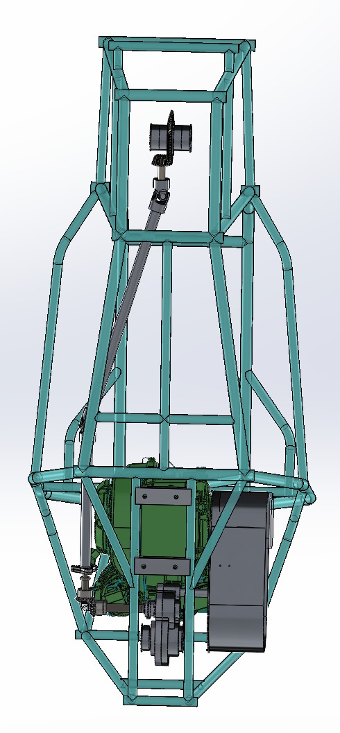
Bottom view of the shaft path, gearbox to front differential.
Two Joints, Equal Angles
A single U-joint running at an angle does not turn at a constant speed. Even if the input spins perfectly steadily, the output speeds up and slows down twice every revolution, and the bigger the angle, the bigger the swing. On a drive shaft that becomes vibration, and extra load on the joints, the gearbox, and the differential.
The fix is to use two joints at equal angles. The first joint makes the middle shaft speed up and slow down; the second joint, set at the same angle and phased to mirror the first, adds exactly the opposite variation. The two cancel out, so the front differential receives the same smooth rotation that left the gearbox. That is why the geometry is built around one joint at each end of the long section, both running at the same angle.
Why Equal Angles Matter
- Operating angle at each joint: about 16.2°.
- For a single joint at that angle, the output speed swings between roughly 96% and 104% of the input speed (between cos 16.2° and 1 / cos 16.2°), twice per revolution.
- With a second joint at an equal angle, the two swings cancel, and the differential sees a constant speed.
The same ~4% swing that cancels at the differential still exists inside the middle section of the shaft, which is one of the loads the stress analysis has to account for.
Custom Yokes, Two Materials
The shaft joins two metals. The short stub leaving the gearbox is 4140 chromoly steel, because it carries the splines that engage the gearbox output, and aluminum can't hold a spline under this kind of load. The long main section is a 6061 aluminum tube, 1 inch in diameter with a 1/8 inch wall, to save weight over the length of the car.
Each yoke is welded to its shaft, and steel can't be welded to aluminum, so each yoke has to be made from the same metal as the shaft it joins: a steel yoke on the steel stub, and an aluminum yoke on the aluminum tube. Off-the-shelf U-joints don't come in that combination at a 1 inch size, so I designed the yokes myself around a purchased cross from All Balls Racing. Buying the cross keeps the precision bearing part off-the-shelf, while the custom yokes solve the size and material problem.
The U-joint in 3D: steel stub and yoke, aluminum yoke and tube. Drag to rotate, scroll to zoom.
Validation (In Progress)
The car can't drive without this shaft, so it has to be proven before it goes on. My feasibility calculations show the design works; I'm now checking it much harder in SolidWorks Simulation before anything is manufactured. The things I'm considering in the analysis:
- Shock loads, not just steady torque. Off-road driving hits the drive line with sudden torque spikes, such as landing a jump with the throttle open or a wheel suddenly biting after spinning. The shaft needs to survive those peaks, not just normal driving.
- Welded aluminum. Welding 6061 aluminum weakens the metal next to the weld, well below its normal strength. The weld joints between the yokes and the tube are a key area I'm checking.
- Fatigue. The shaft is loaded and unloaded every revolution, over a full endurance race, so it has to hold up to repeated loading, not just a single peak.
After the analysis, the plan is physical testing: 3D-printed yoke prototypes paired with bought yokes to check clearances and work out the assembly procedure, and a shock test on a welded aluminum sample before committing to the final parts.
Other Work on the Team
Alongside the drive shaft, I've worked on other parts of the car, including sprag bearing wheel hubs and a redesign of the wheel rims to reduce weight.
Western Combat Robotics (WE First)
As VP Combat Robotics, I lead Western's first combat robotics program. Two teams build competing 1 lb antweights, fight each other to find out which design approach actually works, then carry what they learn into competition against other universities.

Reference photo, not our robot: a 1 lb vertical spinner, the class Build A is aiming for. Photo: Mark Sutton, posted in the Kansas Combat Robotics Facebook group.
Overview
WE First's combat robotics program, Bot Brawl, launched in 2026, and I lead it. Instead of putting every member on one robot, the program runs two parallel builds of roughly 15 people each. Each build has its own lead who reports to me, and each build lead runs mechanical, electrical, and software leads. The two builds take deliberately different design approaches, and once both robots are finished they fight each other.
We compete in the 1 lb (454 g) antweight class. It is small enough that most of the robot can be 3D printed and a broken part costs tens of dollars instead of hundreds, but the engineering is real: brushless weapon motors, LiPo power, radio control, and armour that has to survive a spinner hit. Ontario already has an active 1 lb scene. BotBrawl events run a regular antweight class, and university teams such as Waterloo's WATBOTs, U of T's UTRA, and TMU BattleBots already compete at them in the 1 lb and 3 lb classes. The goal for the end of the 2026–27 year is to join them.
Two Builds, One Design Question
Running two builds only pays off if the two are trying different things, so each team takes a contrasting approach and the internal fights settle it by result rather than by argument. Nothing is locked in yet. The two archetypes below are the front-runners, the pair that most often meets in the antweight class, and they frame the question we actually want answered: for a first-year team with a limited budget, is it better to build the robot that deals the damage or the robot that controls the fight?
Build A
Vertical Spinner
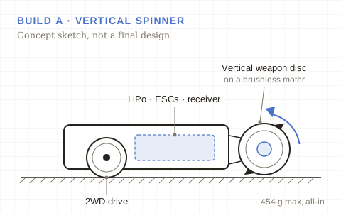
Stores energy in a spinning disc or drum and releases it upward on impact, launching or breaking the opponent. The hard problems are fitting enough weapon energy inside the weight limit, handling the gyroscopic effects on steering, and surviving the recoil of its own hits.
Build B
Wedge / Control Bot
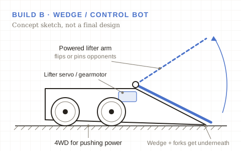
Wins by getting underneath the opponent and controlling the fight, using a wedge and forks to get under and a powered lifter to flip or pin. The hard problems are wedge geometry and ground clearance, enough traction to push, and armour that can take spinner hits, since this robot has to survive the weapon it is fighting.
The Internal Bot Brawl
When both robots are built, they fight each other. After every fight, both teams tear down their robots, record what broke and why, and feed that back into their design. Both teams, not just the winner, then take those lessons into the robots we enter at inter-university competition. The comparison also covers cost and build time as well as fight results, which tells the program which approach a new team can realistically build well.
Reference footage, not our robots: Red Hot, a vertical spinner, fights Snap!, a control bot, in the BotBrawl Robot League. Video: BotBrawl Canada on YouTube, starting at the fight (17:31).
My Role
- Setting the program's technical direction, including the weight class and the direction each build takes.
- Driving the key design decisions on both builds, so the two stay genuinely different and the head-to-head stays a fair test.
- Managing the two build leads, who each run mechanical, electrical, and software leads on a team of about 15.
- Overseeing the budget across both builds: roughly $500 to $800 per robot (early estimate).
- Owning the timeline, so both robots are ready for the internal Bot Brawl with time left to iterate before outside competition.
- Planning the program's entry into inter-university competition in Ontario's 1 lb class.
Sizing the Program
- Weight limit: 1 lb (454 g) per robot, all-in: chassis, weapon, batteries, and electronics.
- Budget: roughly $500 to $800 per robot, or about $1,000 to $1,600 across both builds (early estimate).
- People: about 15 members per build, around 30 in total (early estimate).
- Leadership: 1 program lead, 2 build leads, and 6 subsystem leads.
With two robots on one budget, every dollar spent on one build is a dollar the other can't use. Keeping both teams inside the same per-robot range matters for fairness as well as money: if one robot wins because it was allowed to spend more, the fight doesn't tell us anything about the design.
Season Plan
Tentative, and will change as the builds progress.
-
Fall 2026 · We are here
Launch
Recruit members, form the two teams, appoint build and subsystem leads, and set each build's archetype and budget.
-
Fall 2026
Design
Concept CAD, weight budgets, and design reviews for both builds before parts are ordered.
-
Winter 2027
Build and Test
Fabricate and assemble both robots, then drive and weapon testing.
-
Winter 2027
Internal Bot Brawl
Build A vs Build B, with a teardown and design review after every fight.
-
By the end of 2026–27
Inter-University Competition
Rebuild with what the internal fights taught us, then compete against other schools in Ontario's 1 lb class.
Credits
Top photo by Mark Sutton, from the Kansas Combat Robotics Facebook group. Fight footage by BotBrawl Canada, embedded from YouTube. The robots shown belong to their builders: Red Hot by Hot Sauce and Snap! by Trouble Robotics (details via BuildersDB). The BotBrawl logo and arena photo on my homepage card belong to BotBrawl Canada and are used only to reference the league we plan to compete in; the program is not affiliated with BotBrawl Canada. The concept drawings in this section are my own.
Open-Source 3D Printer Enclosure ("Flush Factory")
An enclosure for the Prusa XL that anyone can build for about $162 in parts: every bracket printed on the printer it encloses, every panel a plain rectangle of hardware-store acrylic, and an active filtration unit running on a $5 filter. Placed 1st in Western's First-Year Engineering Design Competition.
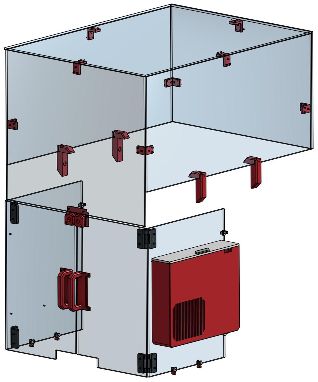
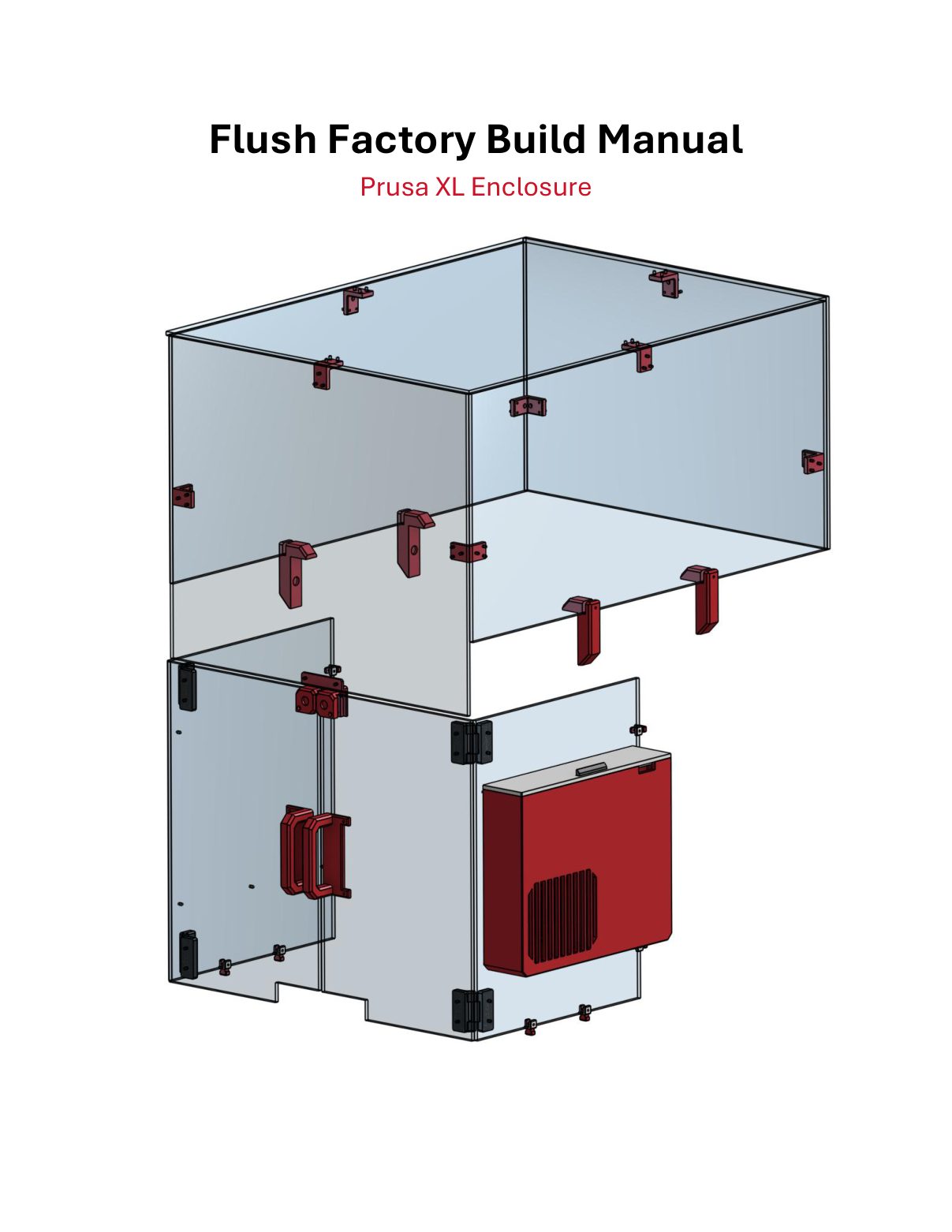
The full assembly: printed parts in red and black, acrylic panels clear.
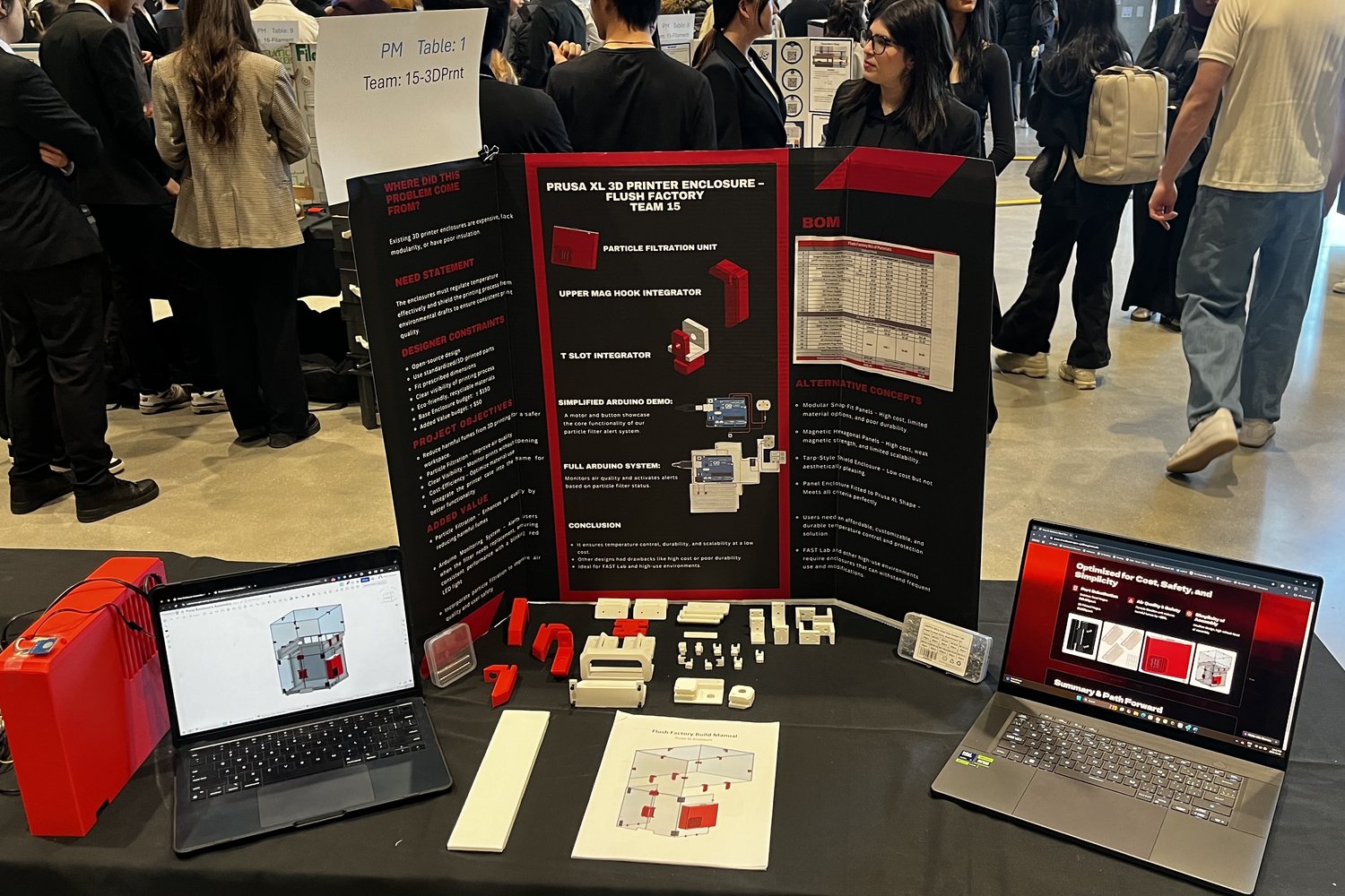
The competition table: printed part kit, fasteners, and build manual.
Overview
Printing without an enclosure means an open bed exposed to room drafts and a workspace breathing whatever the hotend gives off. The enclosures that fix this are expensive, rarely modular, and often insulate poorly, which is why the makerspaces that need them most tend not to have them. Our brief was Western's FAST Lab: a high-traffic student shop where an enclosure has to survive constant handling and constant modification.
The design constraints were tight and mostly financial: under $150 for the base enclosure, under $50 for whatever value-add we chose to bolt onto it, standardized or 3D printed parts only, recyclable materials, clear sightlines to the print, and an open-source design someone else could actually reproduce. We took the fume problem as the value-add and built an active particle filtration unit into the enclosure itself.
I led the team of five and worked across the whole project rather than owning one subsystem: the CAD for the printed parts, the filtration unit and its control circuit, and the dimensioned build manual we shipped as the deliverable.
Designed to Be Copied, Not Just Built
"Open source" was a constraint we took literally, and it turned out to be the constraint that decided most of the design. Every part had to clear the same bar: could a stranger with one 3D printer, a drill, and no workshop reproduce it? That ruled out laser cutting, welding, custom PCBs, injection-moulded clips, and any proprietary hardware.
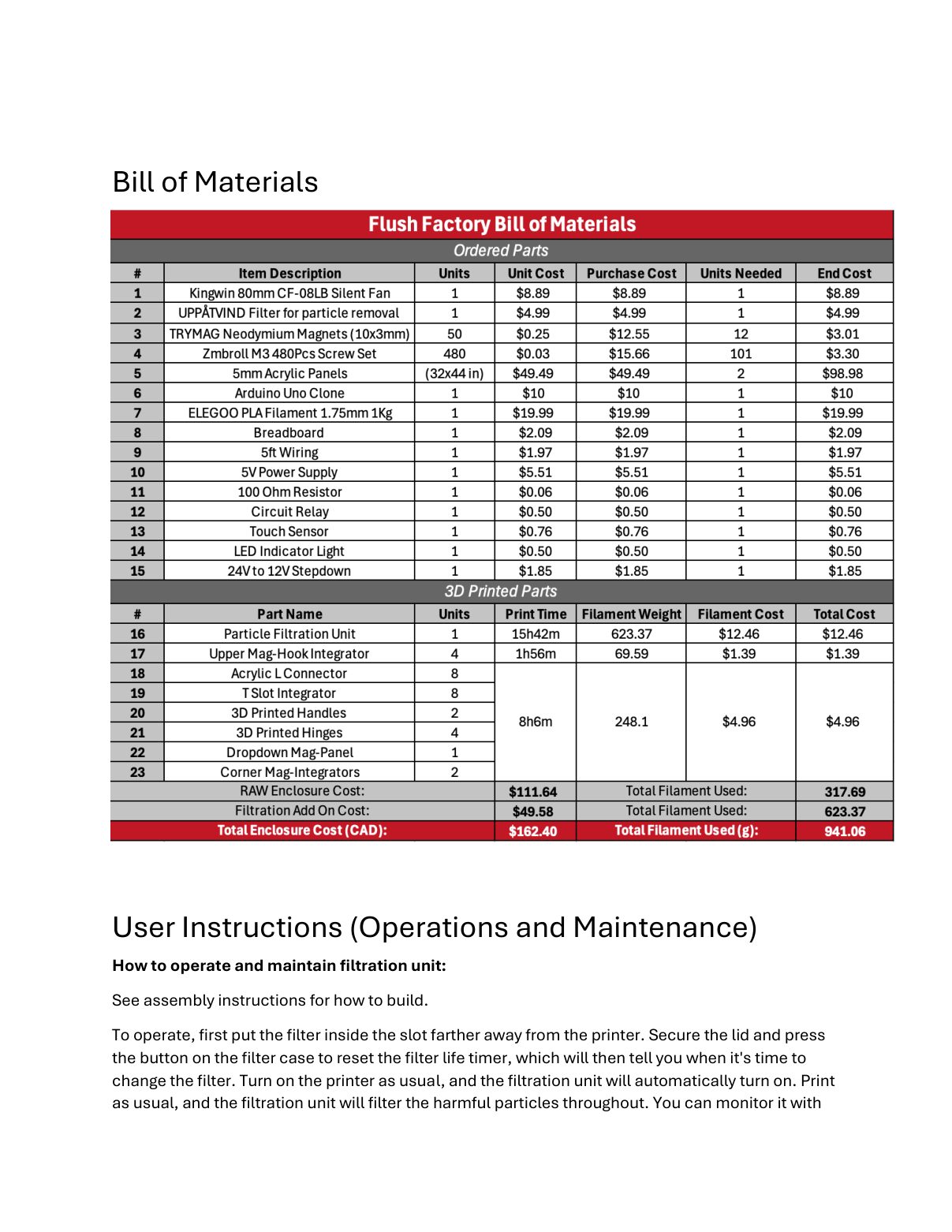
What survived is a parts list you can fill anywhere. The acrylic is nine plain rectangles in six sizes, cut from two sheets by whoever sells them to you, with M3 clearance holes drilled to the dimensions in the manual. The brackets are 30 printed parts across nine designs, all of which fit a standard bed and print in PLA: 941 g of filament, about 26 hours, one spool. The fasteners are M3 screws and 10×3 mm magnets from a bulk pack. Nothing needs a soldering iron.
The other half of it is documentation. CAD files alone are not a reproducible design, so the deliverable was a 23-page build manual: panel drawings with every hole dimensioned, part-by-part assembly renders, a hole-by-hole breadboard wiring guide written for someone who has never wired anything, the full bill of materials with prices, and operating instructions. It is the actual product, and the enclosure is what falls out of following it.
Mounting to the Printer Without Touching It
The hardest requirement to satisfy cheaply was attachment. The enclosure has to hang off a printer we are not allowed to modify, with no drilling, no adhesive, and nothing that voids a warranty on a machine a lab depends on.
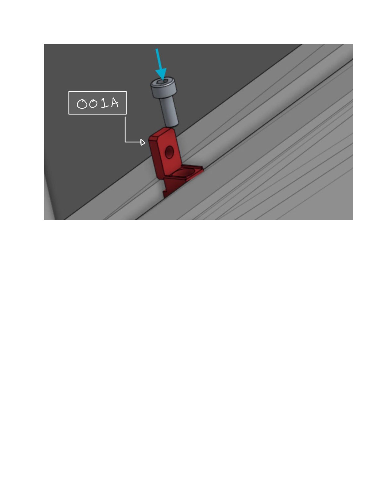
The Prusa XL's frame is extruded aluminum, so the answer was to use the T-slots already in it. Part 001 is a two-piece printed clamp: 001A drops into the channel and rotates 90° to lock, acting as a printed T-nut, and 001B slides on from the outside. A single M3 screw pulls them together and traps the acrylic panel between them. Eight of these carry the structural panels, and the whole enclosure comes off the printer as fast as it went on.
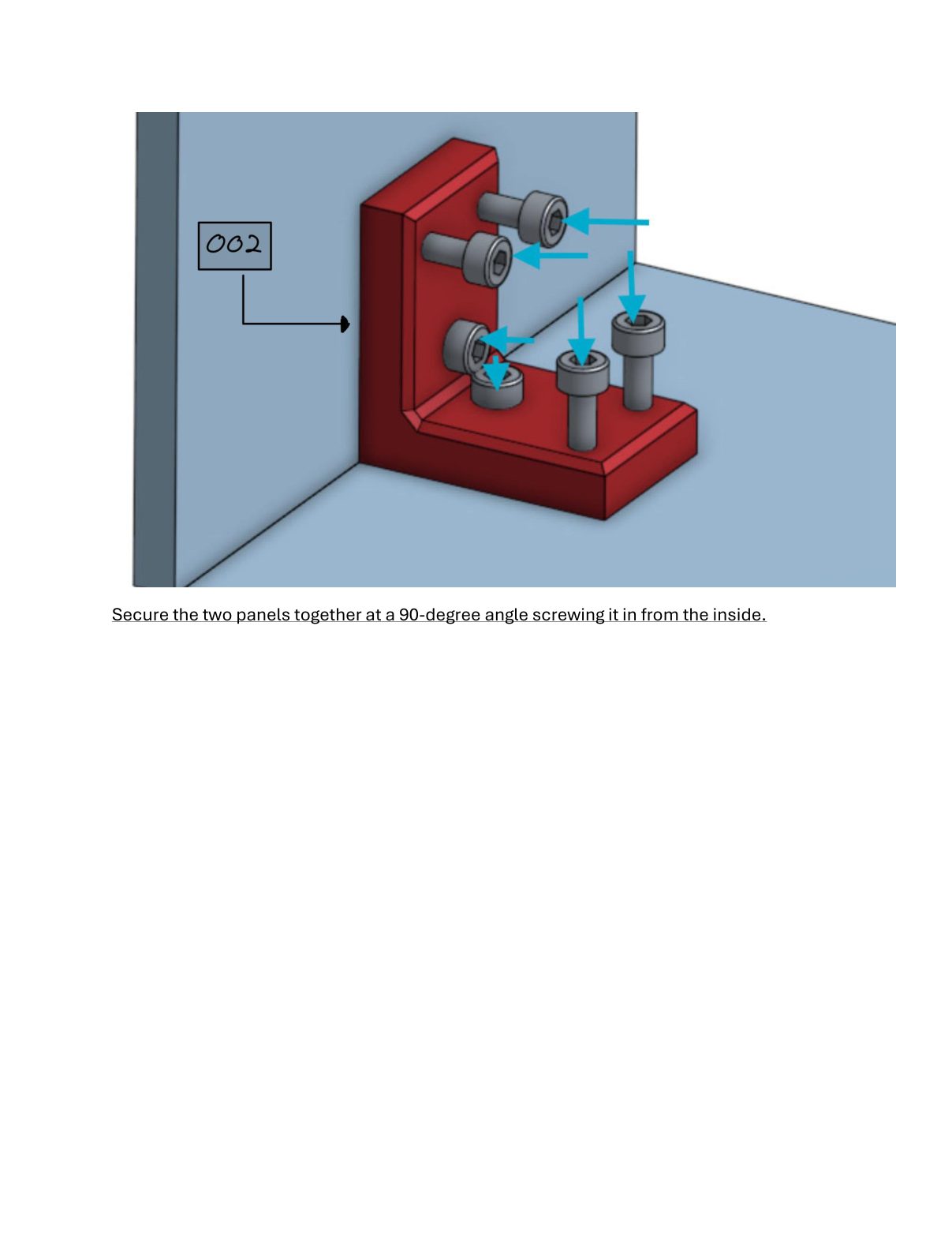
Panels meet each other the same way. An L connector (002) screwed in from the inside holds two sheets at a true 90° without needing a jig, a corner bracket, or a clean edge. The part defines the angle, so the acrylic does not have to.
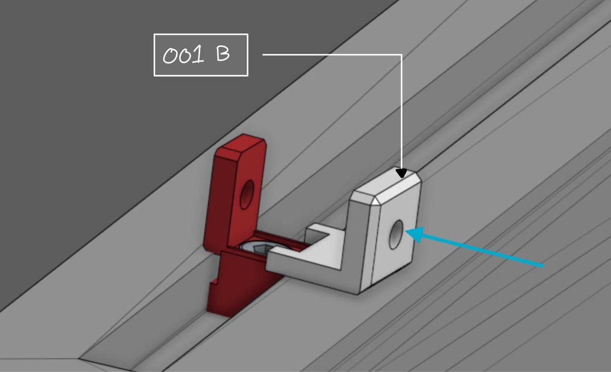
The T-slot integrator clamped into the printer's extrusion.
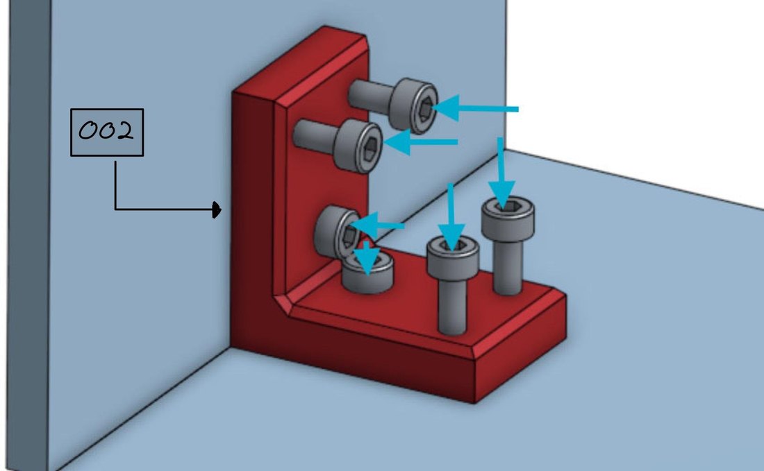
The L connector holding two panels at 90°.
Doors, Magnets, and Seeing In
Every panel is clear for a reason. One of the objectives was monitoring a print without opening anything, because opening the doors dumps the heat the enclosure exists to hold and releases the fumes the filter is busy capturing. A user who can watch the print through the wall does not have a reason to break the seal.
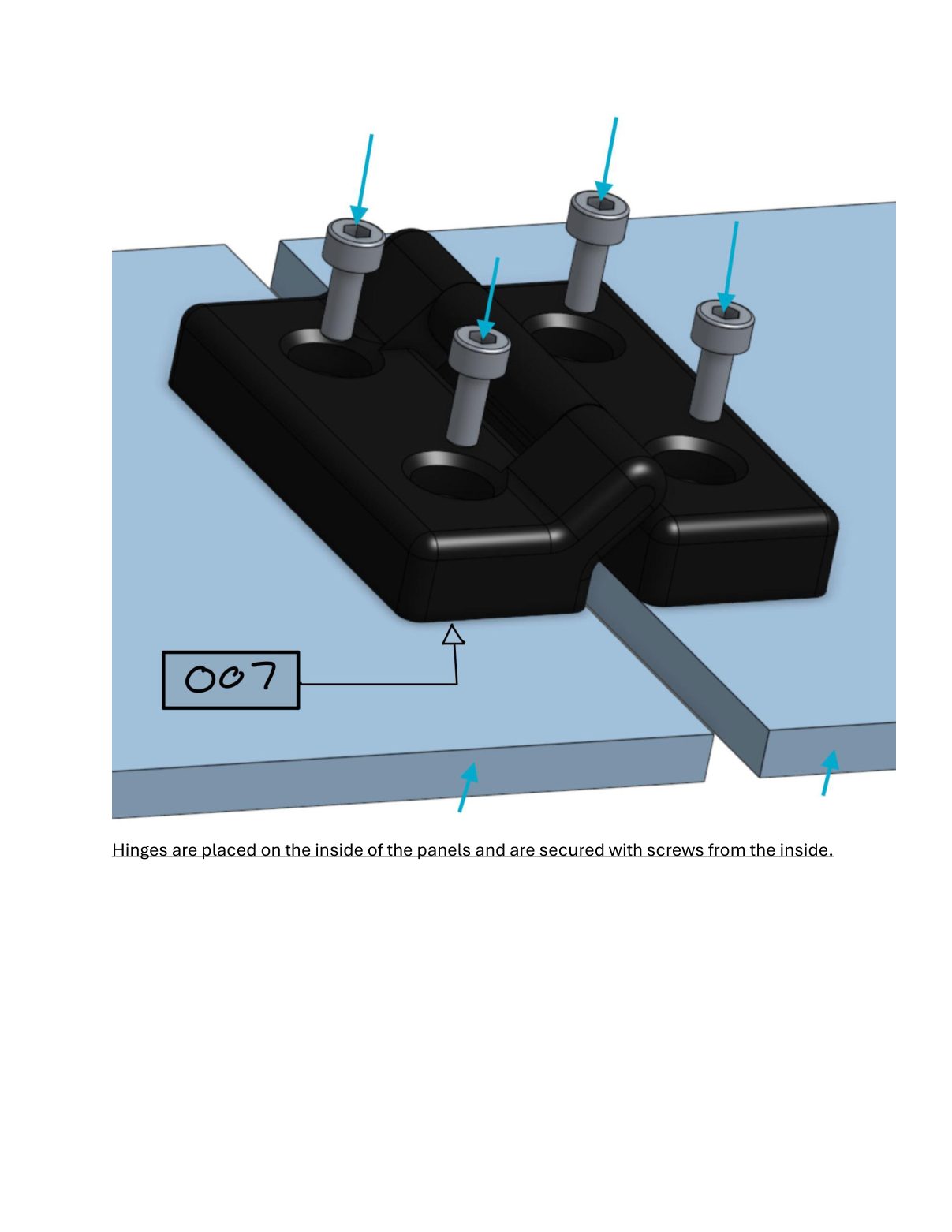
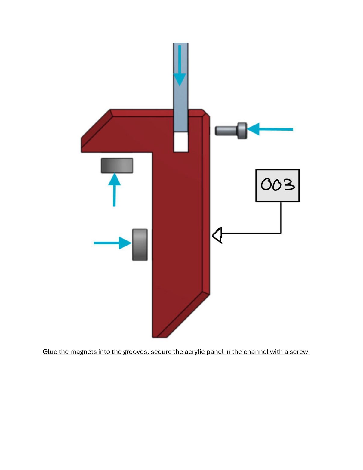
The front doors run on printed hinges (007) mounted on the inside face and close onto neodymium magnets rather than any kind of latch. The magnets are glued into grooves in two printed holders: a corner holder (009) on the frame and a drop-down holder (008) on the door. The closing force comes from twelve $0.25 magnets and two printed parts instead of hardware nobody can source. Printed handles (004) bolt through both faces of each door.
The practical benefit is that the doors cannot bind. A magnetic closure has no alignment to lose and nothing to wear out of adjustment, and a door that pops open under a pull anywhere along its edge is the right failure mode for a lab where people are reaching in with one hand full.
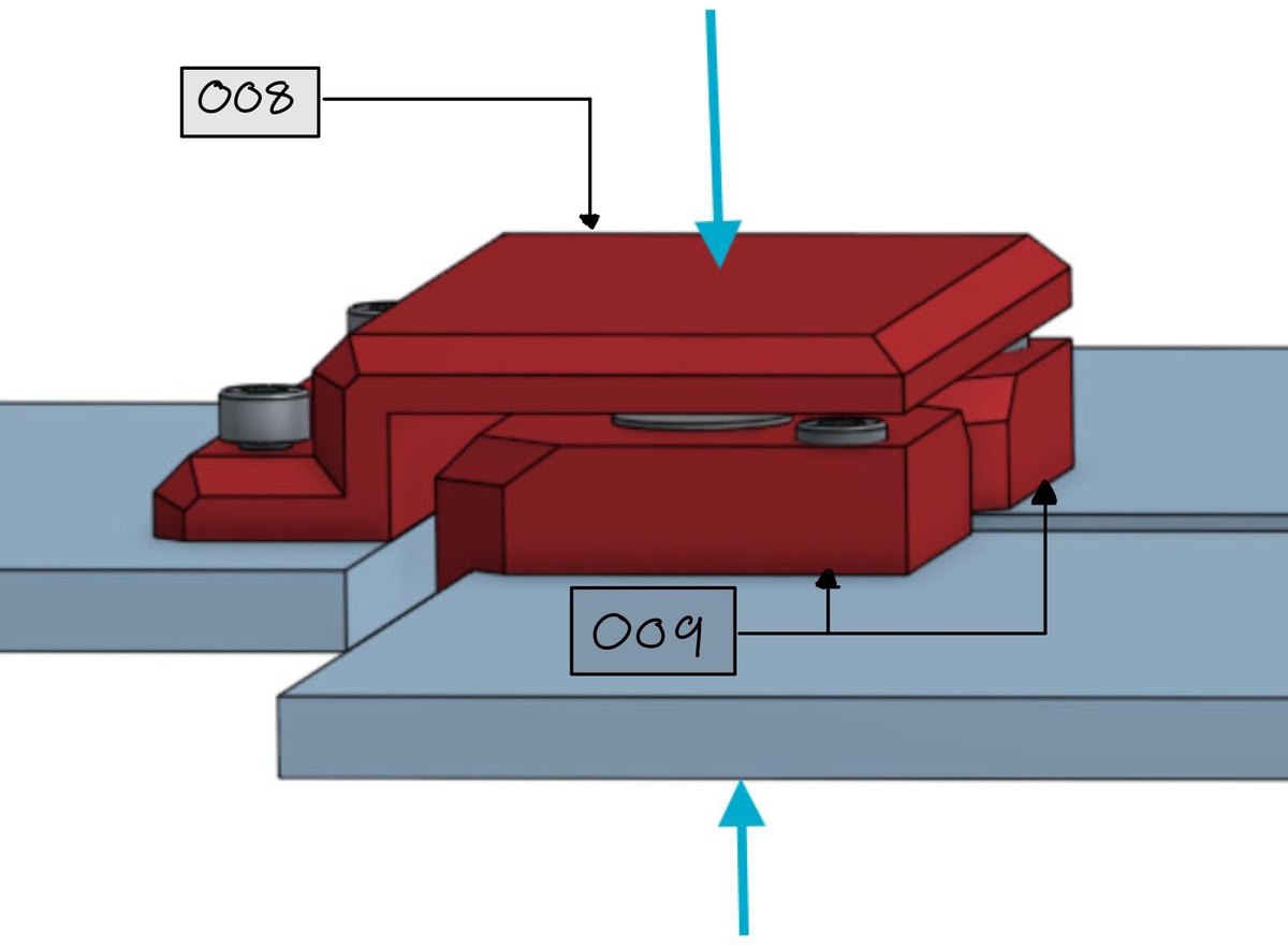
The two magnet holders meeting as a door closes.
The Filtration Unit
The value-add had a $50 ceiling, which is roughly what a single replacement cartridge costs on a commercial fume filter. So the unit is built around a filter you can buy at IKEA: an UPPÅTVIND air-purifier refill, $4.99, stocked in most of the world.
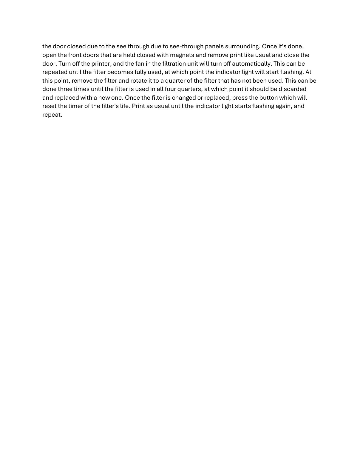
A printed housing (005 body, 006 lid) bolts to a side panel and holds the filter in a slot in front of an 80 mm silent fan, pulling enclosure air through the media instead of letting it drift into the room. Because the filter is square and only the quarter in front of the fan loads up, the housing lets you pull it out and rotate it 90° when it is spent. Four positions, four filter lives, one $5 part, which is the difference between a consumable people replace and one they quietly stop replacing.
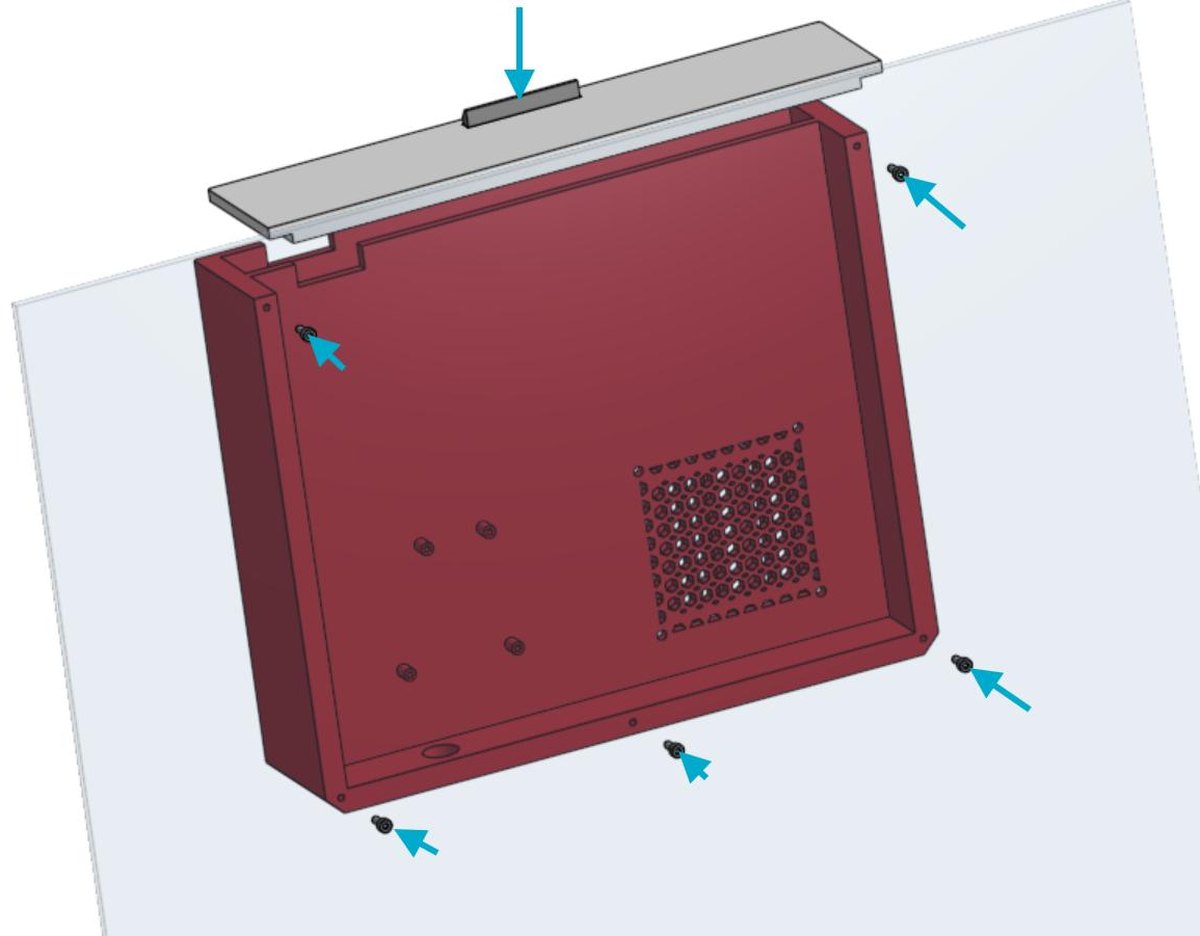
The filtration housing and lid in a side panel.
Knowing When the Filter Is Done
A filter nobody can see is a filter nobody changes, so an Arduino Uno tracks run time and blinks an LED when the media is used up. A touch sensor resets the timer whenever the filter is rotated or swapped. The fan itself runs through a relay off the printer's power rather than its own switch, so filtration starts when the print starts and stops when the printer does. There is no step in the workflow a user can forget.
The circuit is deliberately unimpressive: a relay, a resistor, an LED, a touch sensor, a step-down converter, and a breadboard. The manual assumes no soldering setup and no experience, and walks the builder through it one breadboard hole at a time. No part in it costs more than $10.
Where the Money Goes
The cost breakdown is the part of this project I would point at first. Of the $111.64 base enclosure, $98.98 is the two sheets of acrylic. Every bracket, hinge, handle, magnet holder, screw and magnet in the structure, the entire designed portion, comes to $12.66. The design is essentially free; what a builder pays for is glazing, at whatever their local price for a sheet happens to be.
| Metric | Result | Requirement |
|---|---|---|
| Base enclosure cost | $111.64 | ≤ $150 |
| Active filtration add-on | $49.58 | ≤ $50 |
| Acrylic share of base cost | 89% | — |
| Printed parts | 30 parts, 9 designs | — |
| Filament and print time | 941 g · ~26 h | — |
| Total build cost (CAD) | $162.40 | — |
The Three Concepts We Threw Out
We scored four enclosure architectures before committing. Modular snap-fit panels were expensive, restricted us to one material, and would not survive a shop. Magnetic hexagonal panels were expensive and relied on magnets strong enough to be a problem, with no obvious way to scale to a different printer. A tarp-style shield was genuinely cheap, and looked it. In a space where the enclosure is also a demonstration of what the lab can make, that mattered.
The winner was the least inventive one: flat panels fitted to the shape the Prusa XL already is. Taking the printer's own geometry as the frame meant no structural design to get wrong, no material we had to defend, and mounting points already built into the machine. Most of what makes this design cheap is that we let the printer do the structural work.
Build Manual
The full 23-page manual: panel drawings, assembly renders, wiring, bill of materials, and operating instructions.
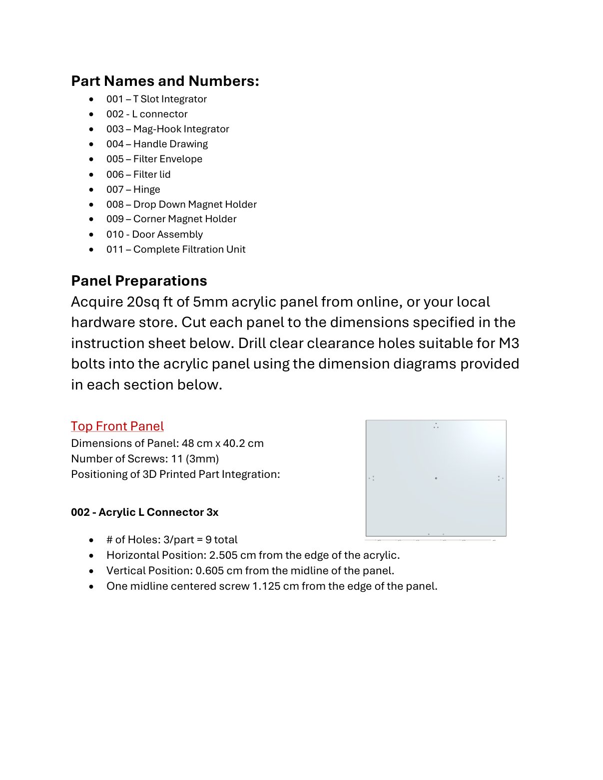
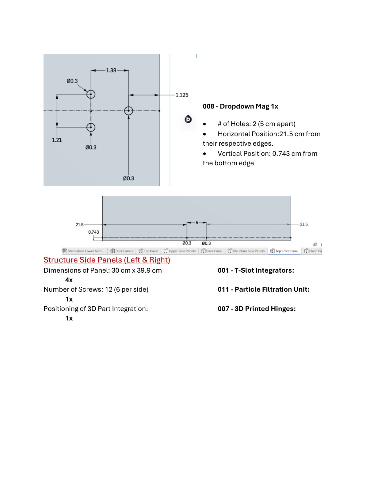
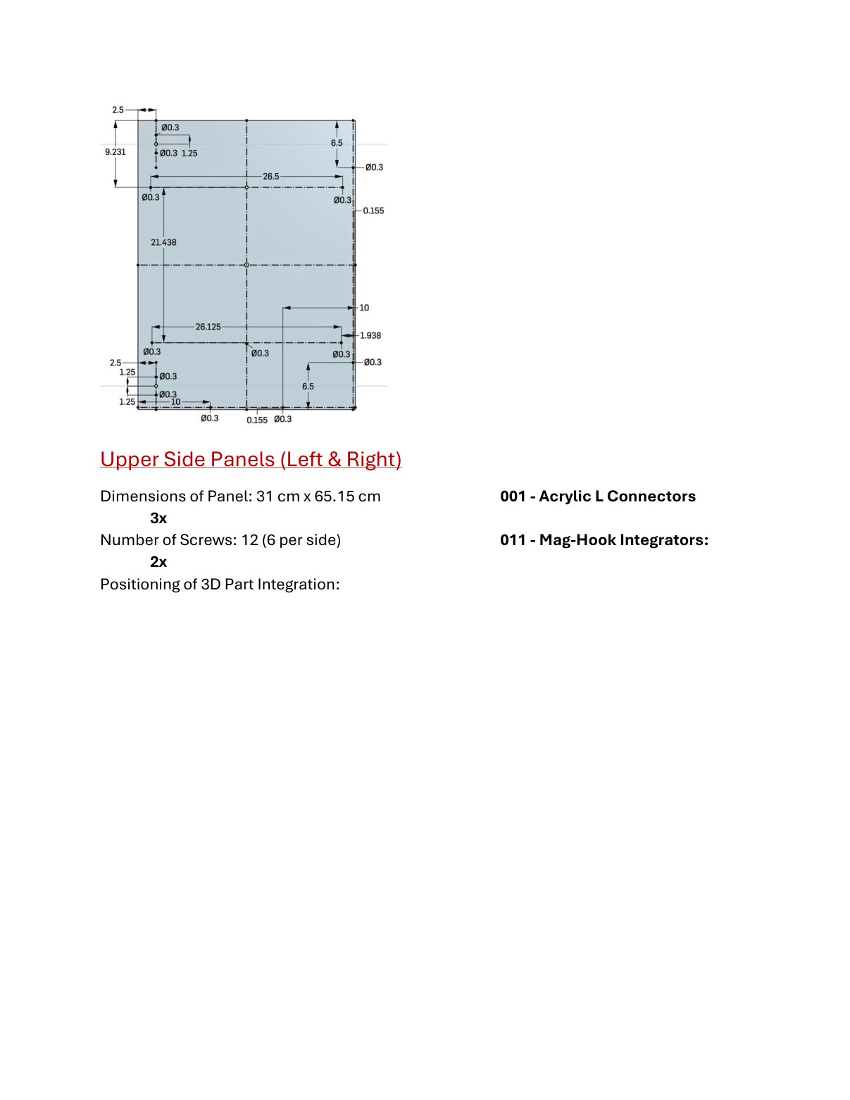
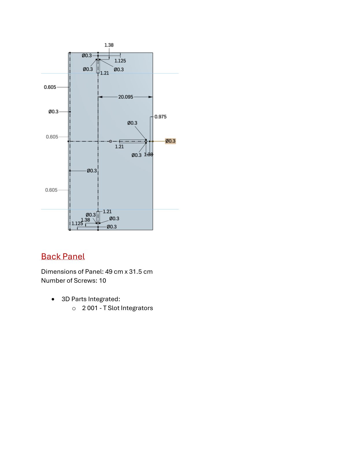
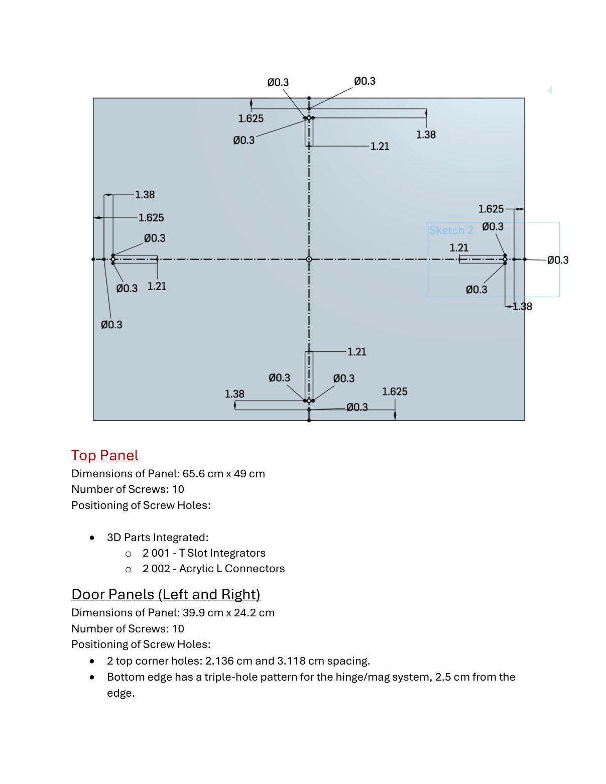
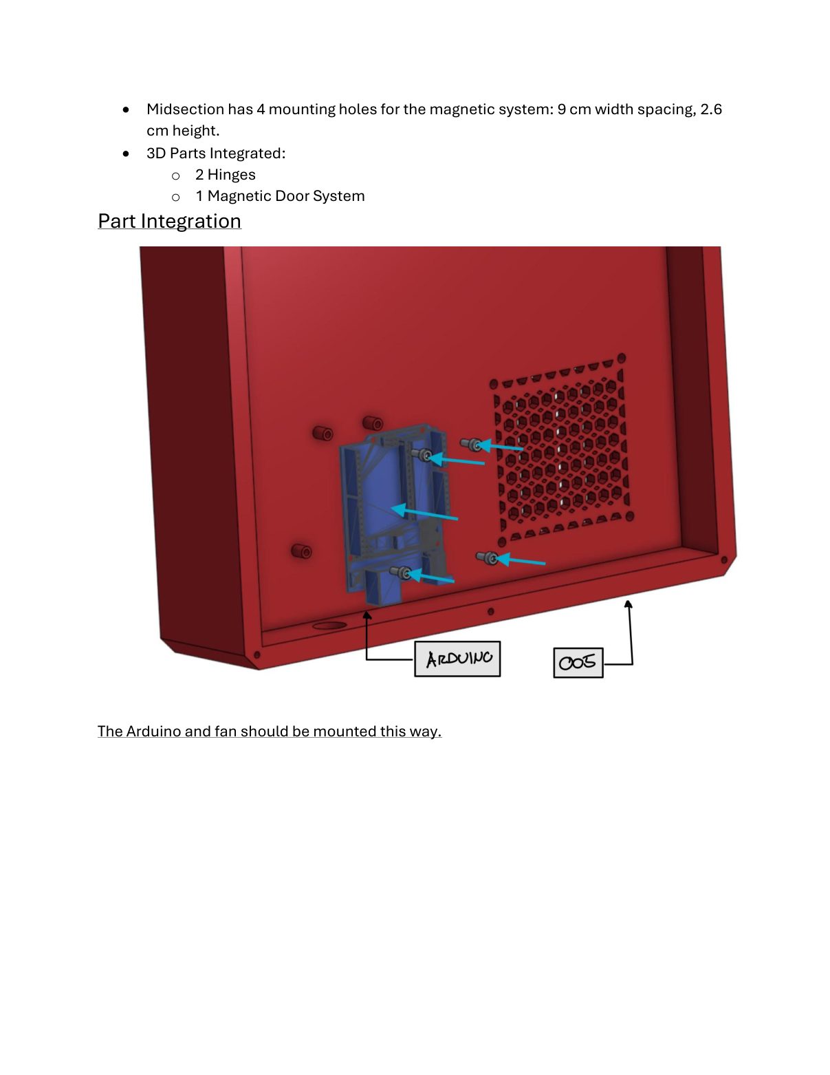
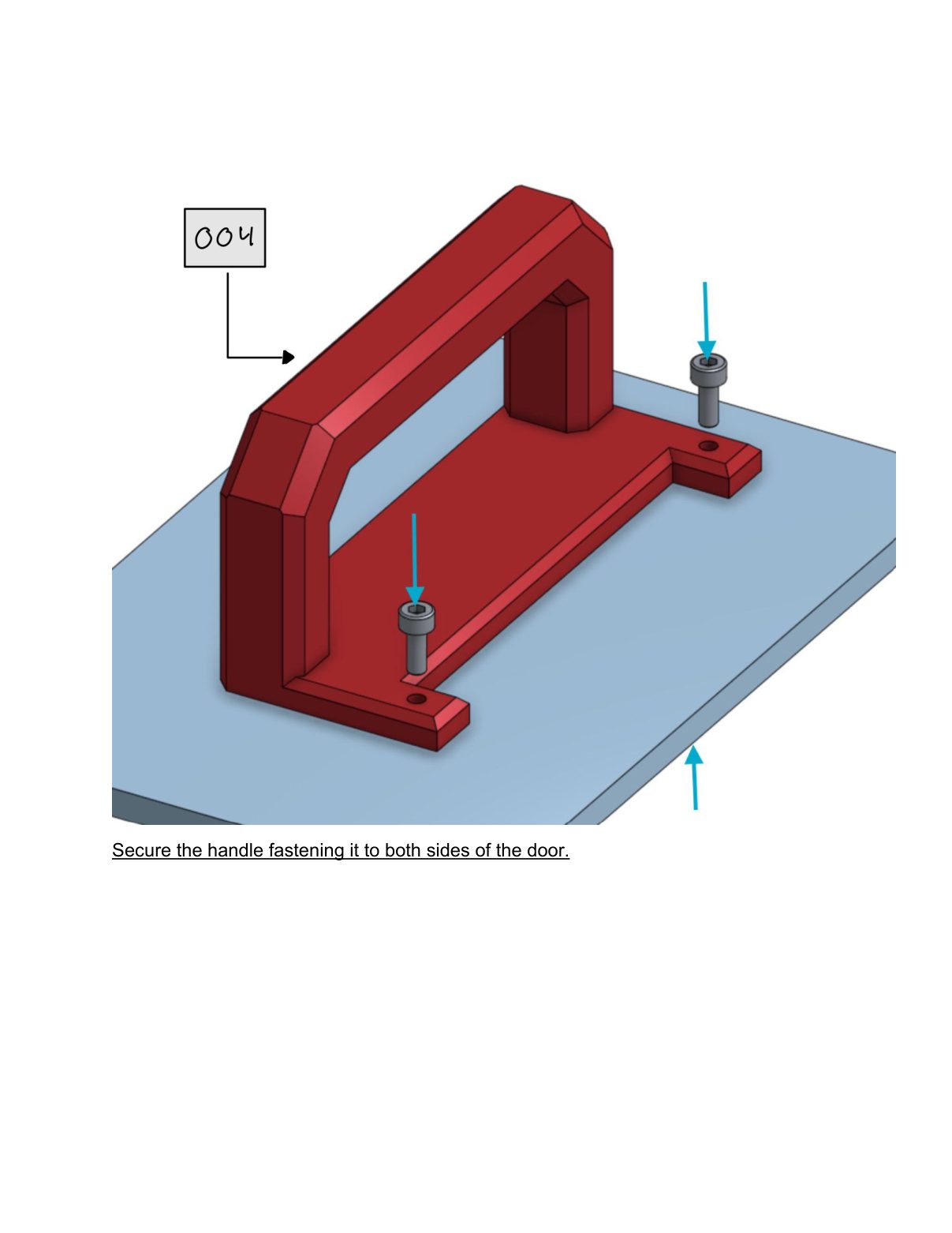
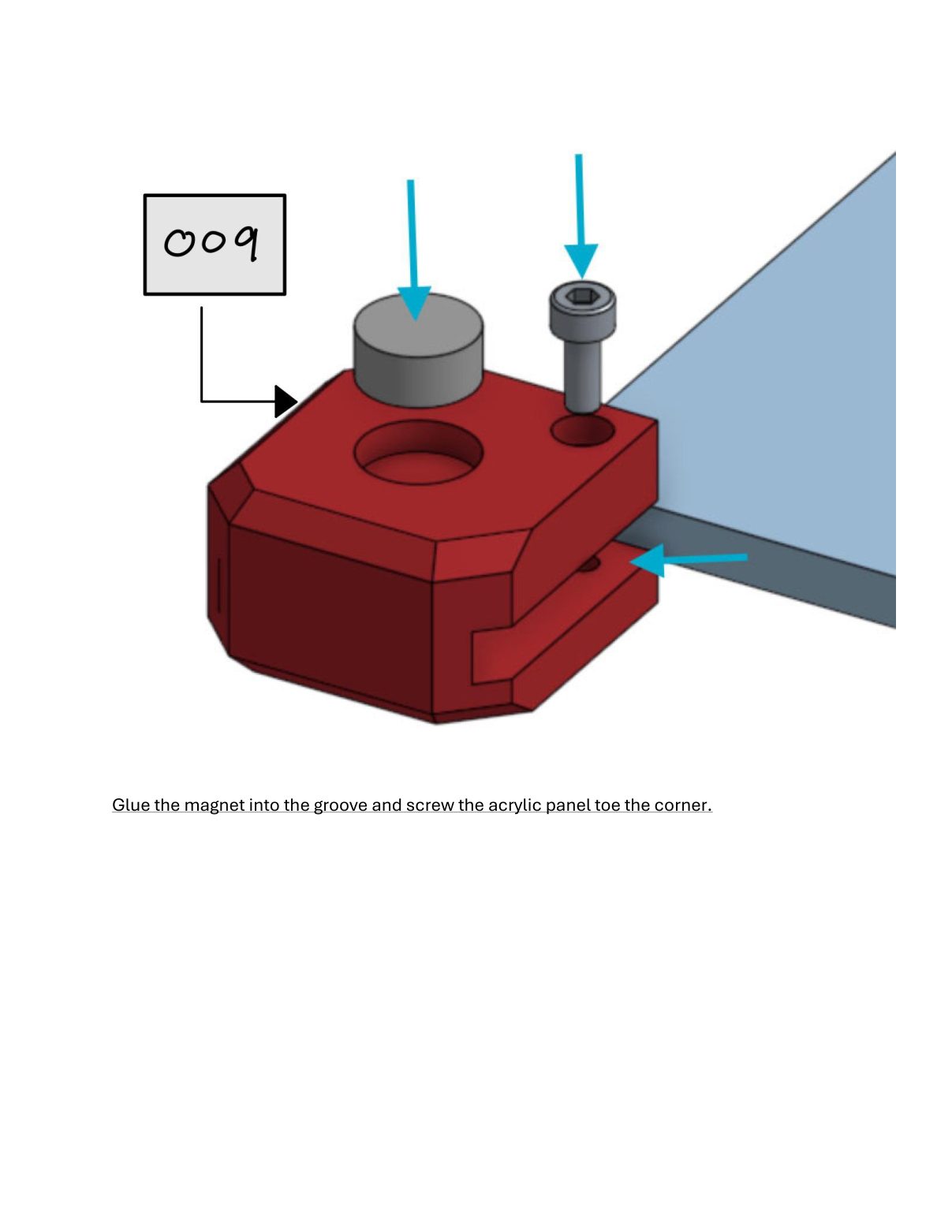
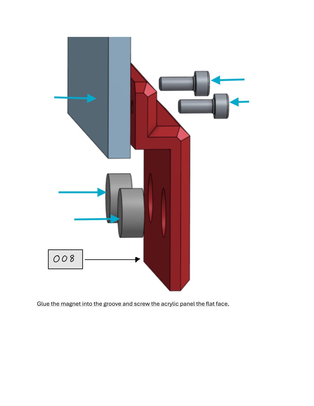
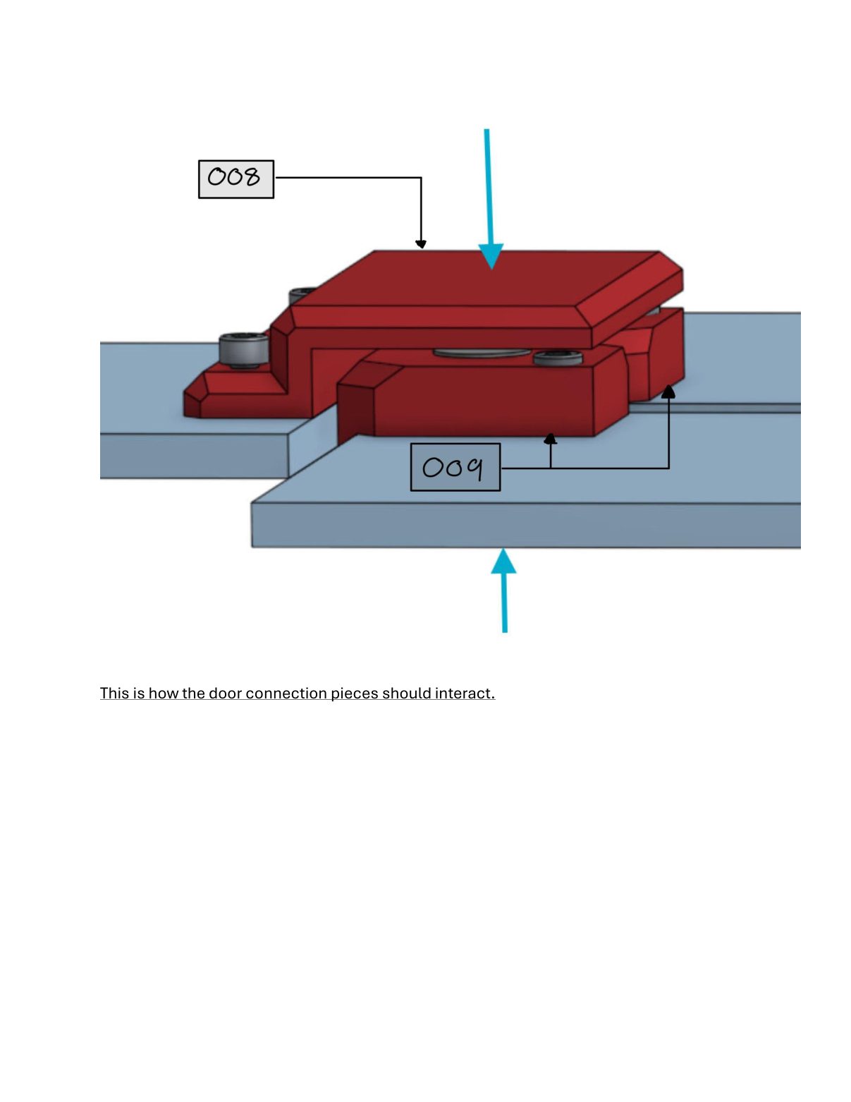
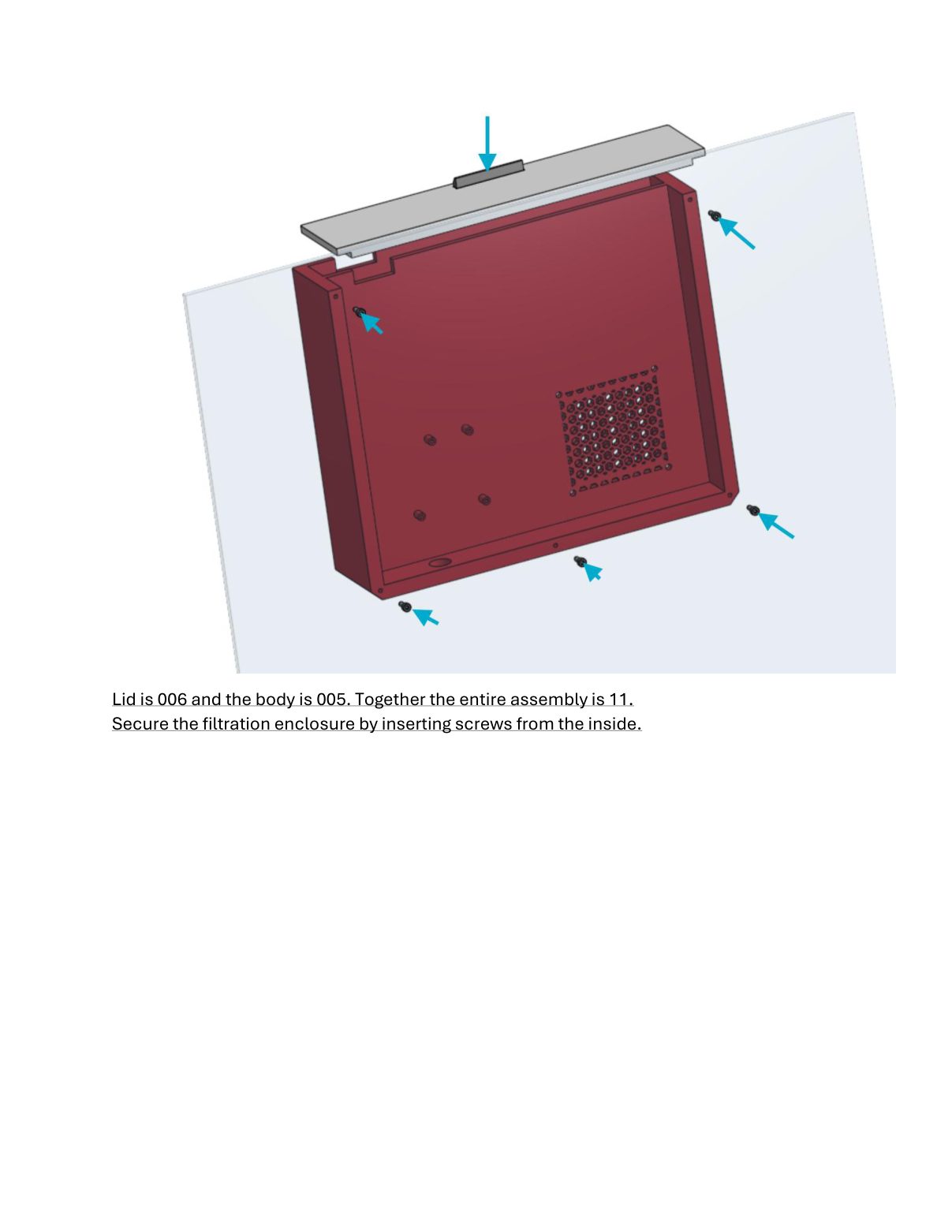
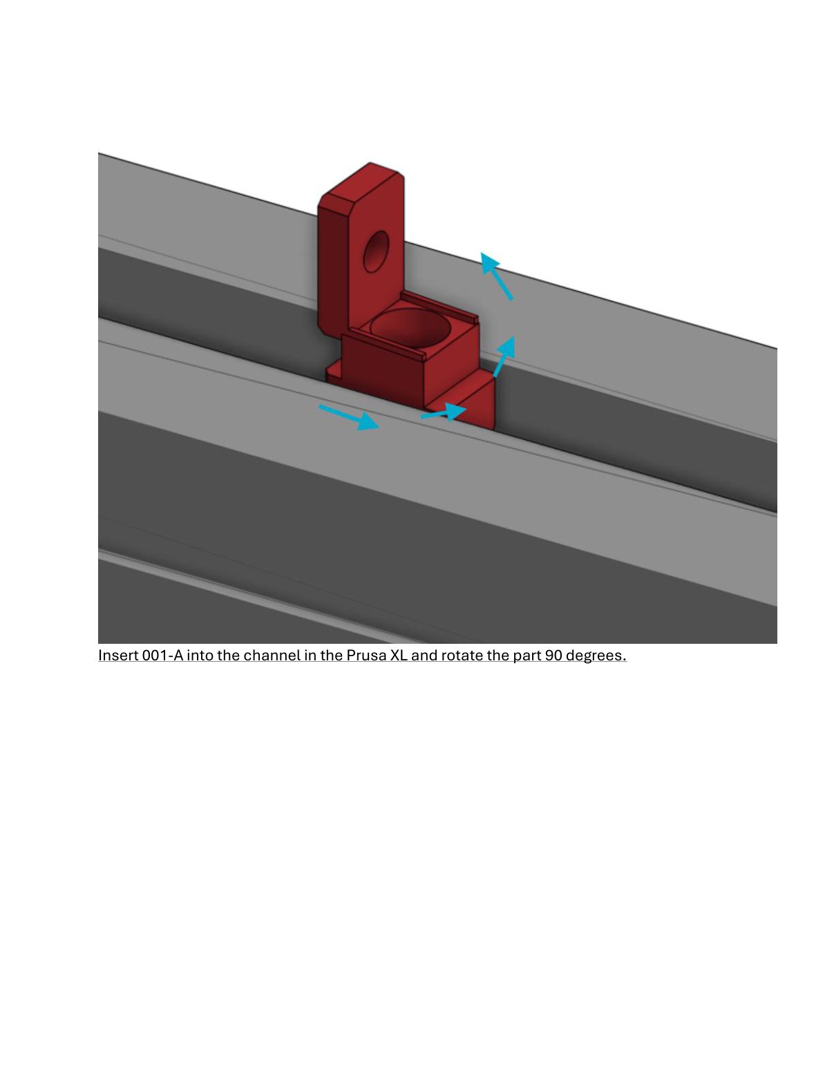
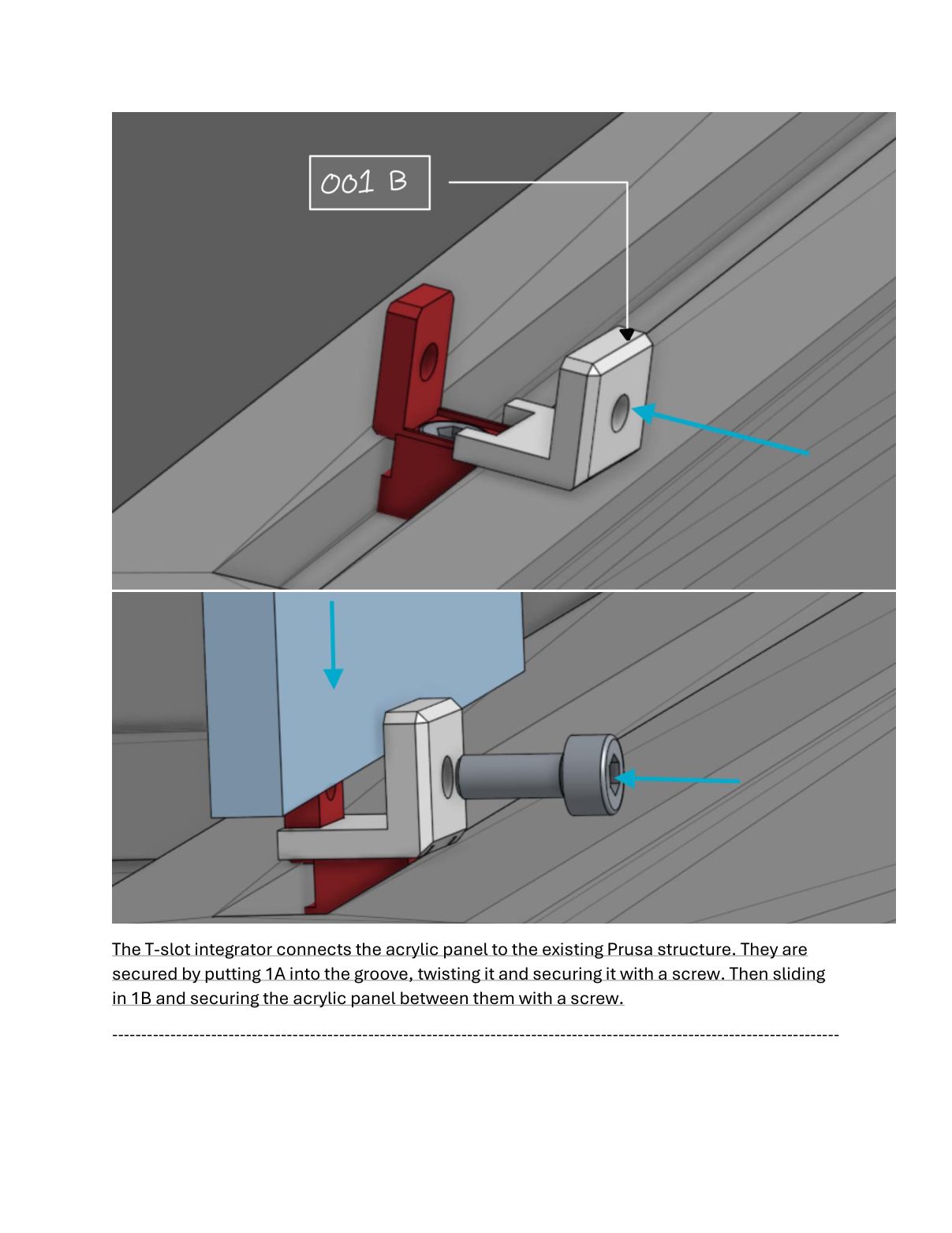
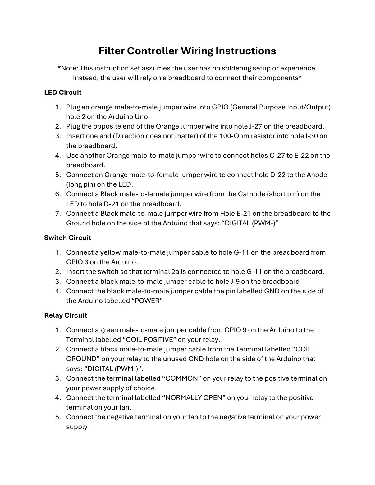

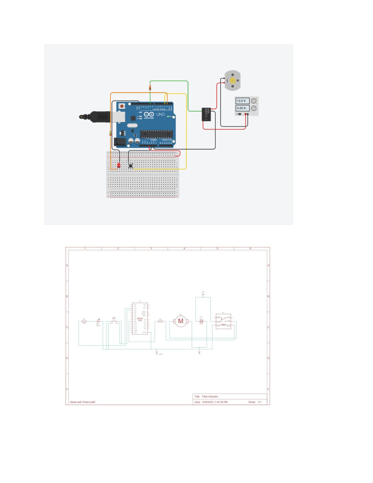
Scroll to read it here, or click to open it full size.
Result
By the end of the term we had printed the complete part kit and built and run the filtration unit and its control circuit; the enclosure shell itself is documented as a cut-and-drill package against the panel drawings. Both budgets held: $111.64 against $150, and $49.58 against $50, with 42 cents to spare.
The project placed 1st in Western's First-Year Engineering Design Competition. What I took from it is that the reproducibility constraint was not a limitation on the design; it was the thing that made it good. Being unable to reach for a laser cutter or a custom part is what pushed us onto the printer's own T-slots and onto a five-dollar filter anyone can find.
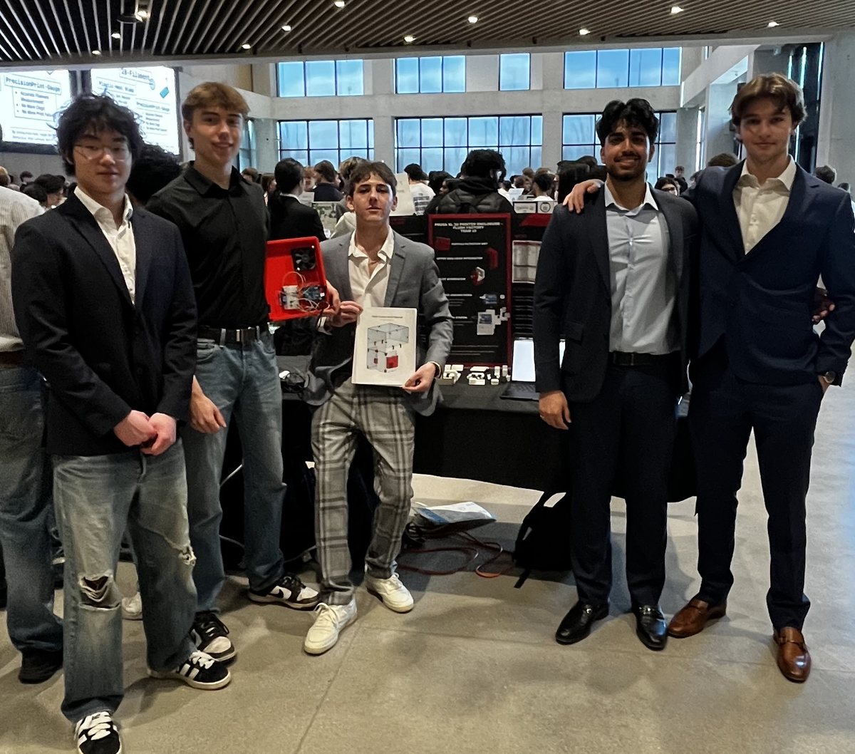
The team at the competition with the filtration unit and manual.
Autonomous IR-Homing Robot
A small autonomous robot that drives a set course, finds an IR beacon, grabs a ping pong ball with its claw, and brings it back to where it started.
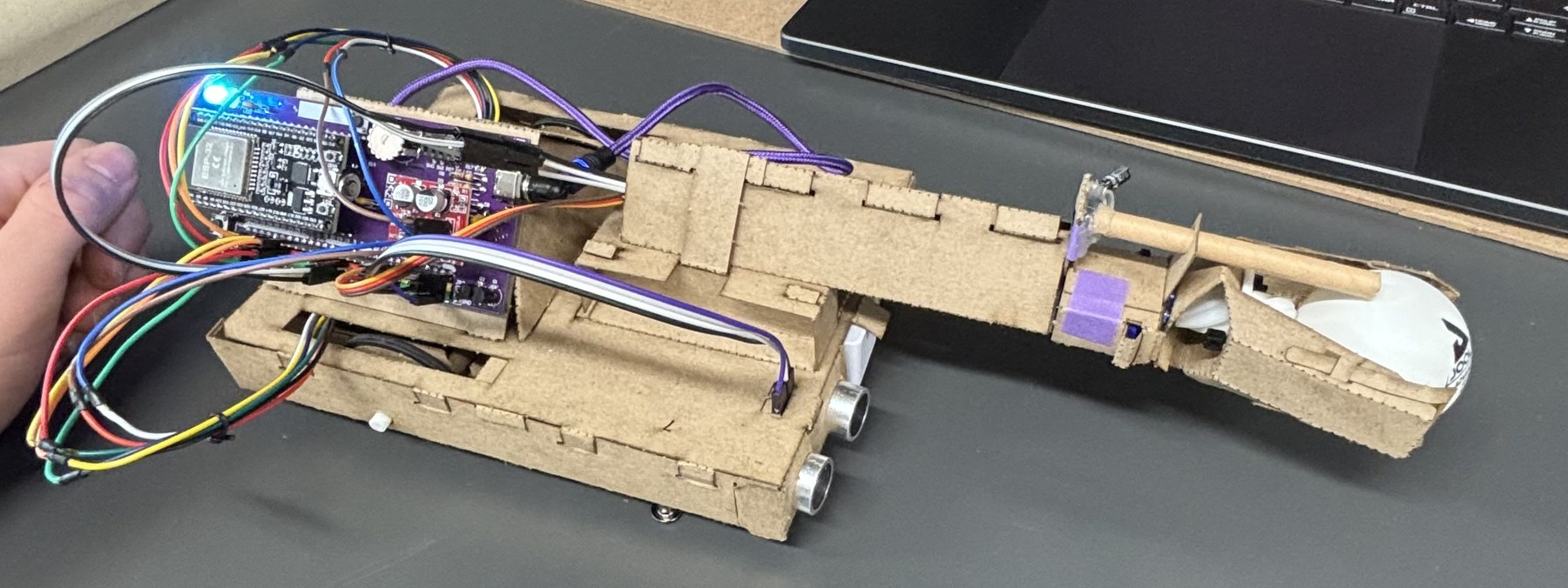
The finished robot: ESP32, ultrasonic sensor, and the claw.
The Task
The course is laid out in taped-together 8.5" × 11" sheets of paper, and the robot has to stay on the paper the whole time. Fully on its own, it has to:
- Drive forward across the first two sheets, then turn 90° counterclockwise.
- Drive across the third sheet and stop.
- Find the ping pong ball on the IR beacon by rotating the chassis and adjusting the arm height.
- Drive in and grab the ball with the claw, using the ultrasonic sensor to avoid crashing into the beacon.
- Return to the start, drop the ball, and stop.
Making It Repeatable
The hard part was getting the robot to move the same way twice. The paper surface was uneven and the wheels had poor grip, so the same drive command could produce noticeably different distances and turn angles from one run to the next, and small errors early in the course added up by the end.
The IR signal was also noisy. Stray readings could pull the robot off target, so steering purely by IR was unreliable.
The approach that worked combined all three: a pre-planned route for the driving legs and the turn, the ultrasonic sensor to judge the distance to the beacon and stop in the right place, and IR only for small final adjustments to line up with the ball. With that combination, the robot grabbed the ball and returned to its starting position successfully and repeatably.
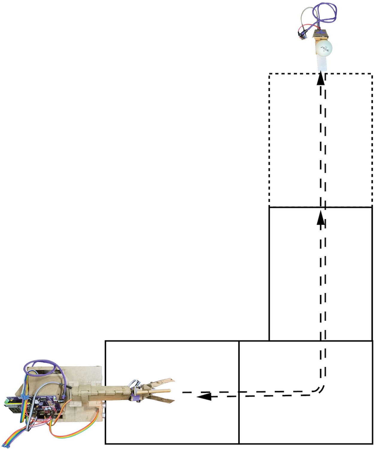
The course: out, a 90° turn to the beacon, and back.
Other Projects
A few smaller projects and experiences. Hover over each for a short description.